Modular paint mist filter

A paint mist filtration and modularization technology, which is applied in the direction of combined devices, dispersed particle filtration, chemical instruments and methods, etc., can solve the problems of complex structure, difficult to remove, high exhaust air humidity, etc., to overcome the replacement of filters, easy disassembly and assembly Effect

Active Publication Date: 2017-12-22
AUTOMOTIVE ENG CORP +1
View PDF7 Cites 0 Cited by
  • Summary
  • Abstract
  • Description
  • Claims
  • Application Information

AI Technical Summary

Problems solved by technology

Although the traditional wet Venturi flume, water cyclone and water curtain technology can achieve continuous separation of paint mist and meet the needs of continuous operations in large batches, this technology will generate a large amount of waste and waste liquid, and because The humidity of the exhaust air is high and dehumidification requires energy consumption, so the energy saving effect of recycling is not obvious
In recent years, some foreign companies have also developed some new dry separation technologies, such as using lime powder to capture overspray paint mist, and then relying on filtration technology to separate solids and gases. This technology consumes a lot of lime powder and contains a lot of paint. Lime powder forms new solid waste that needs to be treated, resulting in increased treatment costs
There are also companies that use electrostatic paint mist separation technology, but this system has the problem of being easily adhered by sprayed objects and difficult to remove
In addition, these devices are complex in structure and expensive, and have been gradually abandoned by automobile painting production lines.

Method used


Image

  • Modular paint mist filter
  • Modular paint mist filter
  • Modular paint mist filter

Examples


Embodiment Construction

[0019] The present invention will be described in further detail below in conjunction with the accompanying drawings and specific embodiments. It should be understood that the specific embodiments described here are only used to explain the present invention, not to limit the present invention.

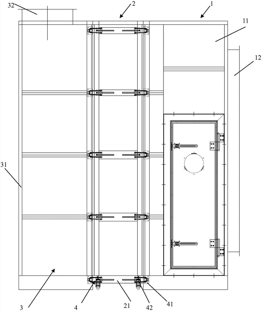
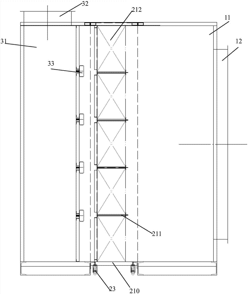
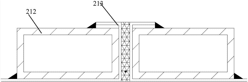
[0020] Such as Figure 1-3 As shown, the modularized paint mist filtering device of the present invention includes a channel-type air inlet section 1, a filter section 2 and a channel-type air outlet section 3, and the air inlet section 1 includes a cavity-type turbulent flow equalization chamber 11 and is arranged on The air inlet 12 on the lateral side, the air outlet section 3 includes a cavity-type air outlet bin 31 and the air outlet 32 ​​arranged on the top of the air outlet bin 31, and the filter section 2 includes a corresponding detachable clamping position The movable frame body 21 between the turbulent flow equalization chamber and the air outlet chamber, the filter part 2...


PUM


Abstract

The invention discloses a modular paint mist filtering device, which comprises an air inlet section, a filter section and an air outlet section, the air inlet section includes an air inlet and a turbulent flow equalizing chamber, and the air outlet section includes an air outlet and the air outlet chamber, the filter section includes a detachable frame body that is detachably and correspondingly snapped and positioned between the turbulent flow equalization chamber and the air outlet chamber, the filter part that is arranged in the movable frame body, and the filter part that is respectively arranged in the movable frame The quick release locking mechanism between the body and the spoiler flow equalization chamber and the air outlet chamber. The filter device of the present invention adopts a negative pressure design, and the gas mixed with paint mist passes through the air inlet section, the filter section and the air outlet section in sequence, and the main body of the filter part is split into a detachable movable frame body, which can conveniently filter the The movable frame body at the bottom is pulled out and replaced, and the movable frame body and the main body are locked by a quick-release locking mechanism, which is extremely convenient for disassembly and assembly, and the replacement time is completed within 3 minutes. Online production can be realized by closing the inlet and outlet valves of the filter device Type replacement, which overcomes the disadvantage that dry filtration cannot replace the filter during production.

Description

technical field [0001] The invention relates to the technical field of automobile painting, in particular to a modular paint mist filtering device. Background technique [0002] The traditional paint mist exhaust gas separation technology is mainly divided into two types: dry type and wet type. Although the traditional wet Venturi flume, water cyclone and water curtain technology can achieve continuous separation of paint mist and meet the needs of continuous operations in large batches, this technology will generate a large amount of waste and waste liquid, and because The humidity of the exhaust air is high and dehumidification requires energy consumption, so the energy saving effect of recycling is not obvious. In recent years, some foreign companies have also developed some new dry separation technologies, such as using lime powder to capture overspray paint mist, and then relying on filtration technology to separate solids and gases. This technology consumes a lot of l...

Claims


Application Information

Patent Timeline
Patent Type & Authority Patents(China)
IPC IPC(8): B01D46/00B01D50/00
CPCB01D46/0006B01D46/0041B01D46/0047B01D50/20
Inventor 张川林涛马力
Owner AUTOMOTIVE ENG CORP
Why Eureka
Try Eureka