Electric tool

A technology of electric tools and circuits, applied in the field of control circuits, can solve problems such as accidental injury, damage to workpieces, and insufficient strength to hold electric tools

Active Publication Date: 2016-07-06
NANJING CHERVON IND
View PDF9 Cites 0 Cited by
  • Summary
  • Abstract
  • Description
  • Claims
  • Application Information

AI Technical Summary

Problems solved by technology

In this case, the motor stops due to a power failure, and it is sudden. At this time, the user’s hand that triggers the operation switch has not been released. The power of the tool is not strong enough. If the power is suddenly turned on again at this time, the motor will run quickly immediately. The user may damage the workpiece because he does not hold the power tool firmly, and may even accidentally injure himself.

Method used


Image

  • Electric tool
  • Electric tool
  • Electric tool

Examples


Embodiment Construction

[0065] The present invention will be specifically introduced below in conjunction with the accompanying drawings and specific embodiments.

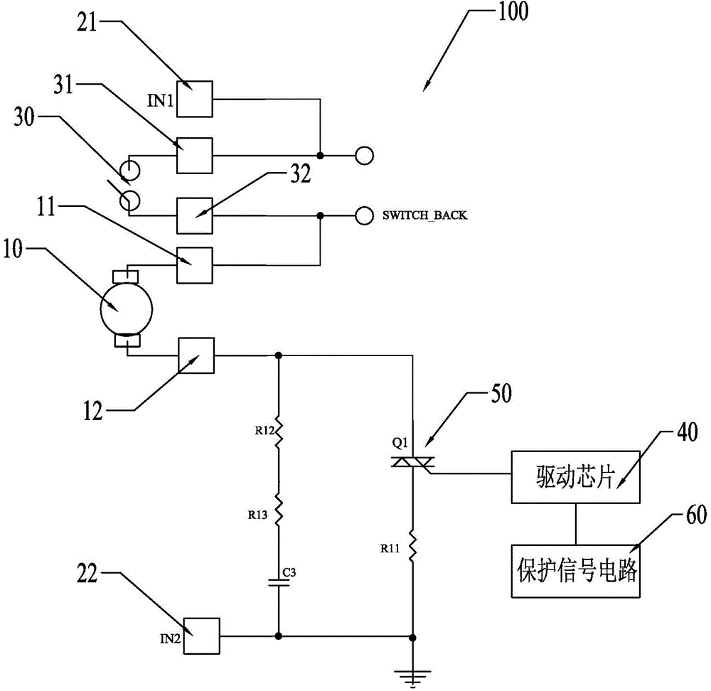
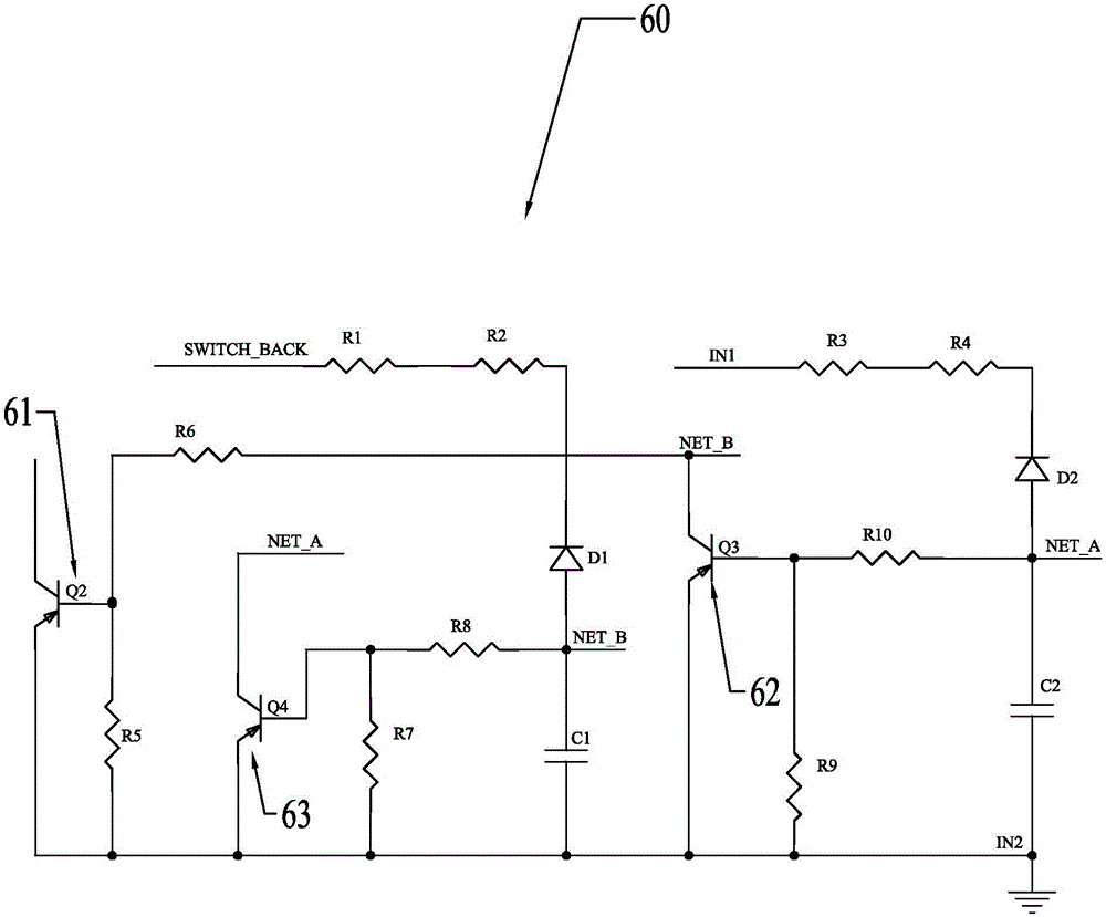
[0066] The present invention proposes an electric tool, figure 1 Shown is the circuit diagram of the electric tool of the present invention; figure 2 shown as figure 1 A circuit diagram of a protective signal circuit in an electric tool, where the protective signal circuit is suitable for an AC electric tool. Please also refer to figure 1 and figure 2 , in this embodiment, taking an AC power tool 100 as an example, the power tool 100 includes: a motor 10, a power terminal group (not shown in the figure), an operation switch 30, a driver chip 40, a protection switch 50 and a protection signal circuit 60 .

[0067] The motor 10 is used to convert electrical energy into mechanical energy to realize the tool function of the electric tool 100 . The motor 10 includes two motor terminals, the two motor terminals are respectively used to ...


PUM


Abstract

The invention discloses an electric tool, and the tool comprises a motor which comprises two motor wiring ends; a power terminal group which comprises two power terminals; an operating switch which has an ON state and an OFF state; a drive chip; a protection switch which has a connection state and a protection state, wherein the connection state and the protection state can be switched by the drive chip; and a protection signal circuit which can generate a protection signal transmitted to the drive chip. The drive chip at least enables the protection switch to enter the protection state when receiving the protection signal. The protection switch enables the circuits connected at two ends to be connected when the protection switch is in the connection state, and cuts off the circuits connected at two ends to be connected when the protection switch is in the protection state. The protection signal circuit generates the protection signal when the tool is operated according to a protection operation sequence, wherein the protection operation sequence is that the operating switch is firstly switched to the ON state and then the power terminals are connected to a power supply. The tool can be started safely.

Description

technical field [0001] The invention relates to an electric tool, in particular to a control circuit in the electric tool. Background technique [0002] With the use of electric tools, people have gradually deepened their research, and one point that cannot be ignored is the safety issue when using electric tools. Usually, we require that the power tool is triggered to work only when the power is turned on and the switch is also turned on. However, for some emergencies, there may still be potential safety hazards in this way. [0003] Especially when the battery pack or the external power supply is suddenly powered off during the use of electric tools and then turned on again. In this case, the motor stops due to a power failure, and it is sudden. At this time, the user’s hand that triggers the operation switch has not been released. The force of the tool is not strong enough. If the power is suddenly turned on again at this time, the motor will run quickly immediately. T...

Claims


Application Information

Patent Timeline
Patent Type & Authority Applications(China)
IPC IPC(8): G05B19/04
Inventor 鲜超王槐树
Owner NANJING CHERVON IND
Why Eureka
Try Eureka