
Safety drilling device for lead-acid battery leakage test

A technology for lead-acid batteries and drilling devices, applied in battery/battery leak testing, boring/drilling, maintenance and safety accessories, etc., capable of solving test errors, contamination of environmental equipment and experimenters, electrolyte splash or overflow To prevent splashing or overflowing, protect the safety of personnel and the environment, and achieve good human-computer interaction

Active Publication Date: 2020-11-24
SHANGHAI RES INST OF CHEM IND +1
View PDF9 Cites 1 Cited by
  • Summary
  • Abstract
  • Description
  • Claims
  • Application Information

AI Technical Summary

Problems solved by technology

[0005] 1. Although the experimenters have personal protective measures, due to the internal pressure, the electrolyte may splash or overflow when the battery is drilled through, which will pollute and damage the environmental equipment and experimenters to a certain extent
[0006] 2. Due to the different wall thicknesses of different types of lead-acid batteries, errors are likely to occur when the battery is drilled through, resulting in the electric drill not stopping after the battery is drilled through, thus touching the electrode plate, resulting in a short circuit
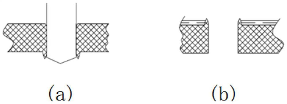
[0007] 3. When using an ordinary drill bit, the contact surface with the battery is likely to generate high temperature due to friction, which will cause the plastic material of the battery shell to soften, and the inner wall of the battery will produce such as image 3 For the ring-shaped protrusion shown in (a), the electrolyte will remain in the cavity during the liquid discharge test, such as image 3 As shown in (b), which in turn causes test error

Method used


Image

  • Safety drilling device for lead-acid battery leakage test
  • Safety drilling device for lead-acid battery leakage test
  • Safety drilling device for lead-acid battery leakage test

Examples


Embodiment

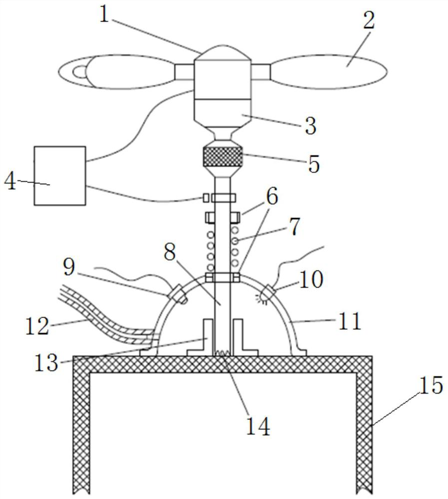
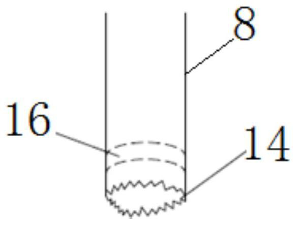
[0035] Such as figure 1 A safe drilling device for the leakage test of the lead-acid battery is shown, including a drilling unit, a protection unit that is sleeved outside the drilling unit and adapted to the surface of the lead-acid battery 15, and a drilling unit that is compatible with the drilling unit. A power-off protection system for the electrical connection of the hole unit. The drilling unit includes a power mechanism and a hollow tube 8 connected to the power mechanism. The bottom end of the hollow tube 8 is provided with sawtooth 14 .

[0036] Wherein, the power mechanism includes a DC motor 1 and a reducer 3 connected to the output shaft of the DC motor 1 , and a connecting head 5 is provided between the reducer 3 and the top of the hollow tube 8 . The serrations 14 are arranged on the bottom end of the hollow tube 8 in a ring shape. A pressing handle 2 is provided on the shell side of the DC motor 1 .

[0037] The protection unit includes a protective cover 11...


PUM


Abstract

The invention relates to a safety drilling device for a lead-acid battery leakage test. The safety drilling device comprises a drilling unit, a protection unit and a power-off protection system, wherein the protection unit sleeves the drilling unit and is matched with the surface of a lead-acid battery, and the power-off protection system is electrically connected with the drilling unit; and the drilling unit comprises a power mechanism and a hollow round pipe in transmission connection with the power mechanism, and sawteeth are arranged at the bottom end of the hollow round pipe. Compared with the prior art, according to the safety drilling device, the sawteeth at the bottom end of the hollow round pipe keep a drilled wafer in the hollow round pipe so that an annular bulge cannot be generated due to high temperature when the inner wall of the battery is drilled through, electrolyte is prevented from being retained in a cavity in the liquid discharge test process, and the test error isreduced; the power-off protection system can realize power-off protection in time; and due to the arrangement of a closed protective cover and a liquid guide pipe, the splashing or overflowing phenomenon possibly occurring when the electrolyte is drilled through can be effectively prevented, and the safety of the personnel environment is protected.

Description

technical field [0001] The invention belongs to the technical field of lead-acid battery leakage test and relates to a safe drilling device for lead-acid battery leakage test. Background technique [0002] Lead-acid battery is a kind of storage battery, which is a kind of storage battery that achieves the effect of repeated use by converting chemical energy and direct current energy into each other, and can be restored after charging after discharge. The electrolyte contains toxic or corrosive substances such as sulfuric acid and lead sulfate, and the battery also contains lead, lead dioxide, lead sulfate, cadmium, arsenic and other harmful substances that endanger human health and the ecological environment. [0003] The leakage test is a test for the transportation conditions of lead-acid batteries. According to the regulations in the "Dangerous Goods Regulations" (IATA DGR) formulated by the International Air Transport Association, if the lead-acid batteries containing el...

Claims


Application Information

Patent Timeline
IPC IPC(8): B23B41/00B23B47/00B23Q11/08H01M10/42
CPCB23B41/00B23B47/00B23Q11/08H01M10/4228Y02E60/10
Inventor 何源李哲吴辰强张小沁冯俊董茜
Owner SHANGHAI RES INST OF CHEM IND
Learn More