
Method of switching an optical signal in an optical flex grid network

A flexible grid, optical signal technology, applied in multiplexing communications, optical multiplexing systems, selection devices for multiplexing systems, etc., can solve the problem of not being able to offset signal impairments

Inactive Publication Date: 2016-07-06
ALCATEL LUCENT SAS
View PDF4 Cites 3 Cited by
  • Summary
  • Abstract
  • Description
  • Claims
  • Application Information

AI Technical Summary

Problems solved by technology

While optical signals can carry data encoded using forward error correction (FEC), such FEC is not capable of counteracting any amount of signal impairment experienced by the transmitted filtered optical signal
[0005] Therefore, the filter function applied by the fixed grid WSS device limits the number of network nodes that the optical signal can pass through in the optical fixed grid network

Method used


Image

  • Method of switching an optical signal in an optical flex grid network
  • Method of switching an optical signal in an optical flex grid network
  • Method of switching an optical signal in an optical flex grid network

Examples


Embodiment Construction

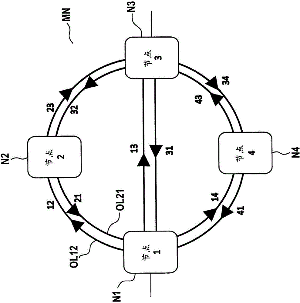
[0037] figure 1 A mesh network MN is shown in which different optical network nodes N1 , N2 , N3 , N4 are connected by different optical links such as eg optical link OL12 or optical link OL21 . At the optical link, the transmission direction is in figure 1 Inside is indicated by different arrows pointing in the corresponding transport direction.

[0038] Preferably, node N1 and node N3 are add-drop multiplexing nodes, while node N2 and node N4 are cross-connect nodes. The network nodes additionally mentioned below in this document may be add / drop multiplex nodes or cross-connect nodes.

[0039] An optical connection from one of these nodes (e.g. node N1) to another of these nodes (e.g. node N3) can be established by a so-called optical path, which goes from Node N1 to node N2 and then travels from node N2 to node N3 via the optical link with index 23 . It can be assumed that the wavelength of the optical signal transmitted at node N1 in the direction towards node N3 along...


PUM


Abstract

Proposed is a method of switching an optical signal in an optical flex grid network. An allocation of a first optical signal to a first spectral slot of the grid at an input port of an optical node is asserted, and an output port of the node to which the first optical signal shall be switched at the node is asserted. An allocation status of a second, next neighbouring spectral slot at the input port of the node is determined. Control instructions are generated that request for switching at least the first signal from the input port to the output port at the node node by a flex grid WSS via a continuous filter function comprising at least the spectral slices of said first spectral slot. The filter function comprises one or more spectral slices of the second spectral slot in dependence on the determined allocation status.

Description

technical field [0001] The present invention relates to a method of switching one or more optical signals in an optical flexgrid network. More particularly, the present invention relates to methods, network controllers, network nodes and networks for switching optical signals in an optical flexible grid network. Background technique [0002] For optical networks having the shape of a mesh network, it is well known to distribute optical signals to fixed optical grid spectral slots along one or more optical links. In such a fixed optical grid, each optical signal can be transmitted within a fixed, predetermined bandwidth spectral slot, where all spectral slots have the same bandwidth. The transmission bandwidth of an optical signal assigned to a particular spectral slot depends on the signal experienced by this optical signal during its transmission along an optical connection (often referred to as an optical optical path) from a sending node to a receiving node via one or mo...

Claims


Application Information

Patent Timeline
IPC IPC(8): H04Q11/00
CPCH04Q11/0005H04J14/0201H04J14/0212H04J14/0271H04Q11/0062H04Q2011/0009H04Q2011/0039H04Q2011/0041H04Q2011/0052H04Q2011/0088
Inventor F·布查利
Owner ALCATEL LUCENT SAS
Learn More