
A new type of shrapnel puller

A technology of shrapnel and fins, applied in the field of zipper, can solve the problems of many parts and complex structure, etc.

Active Publication Date: 2019-02-19
IDEAL FASTENER GUANG DONG IND LTD
View PDF5 Cites 2 Cited by
  • Summary
  • Abstract
  • Description
  • Claims
  • Application Information

AI Technical Summary

Problems solved by technology

The technical scheme disclosed in this patent has a complex structure and many parts

Method used


Image

  • A new type of shrapnel puller
  • A new type of shrapnel puller
  • A new type of shrapnel puller

Examples


Embodiment Construction

[0037] The specific embodiment of the present invention will be further described below in conjunction with accompanying drawing:

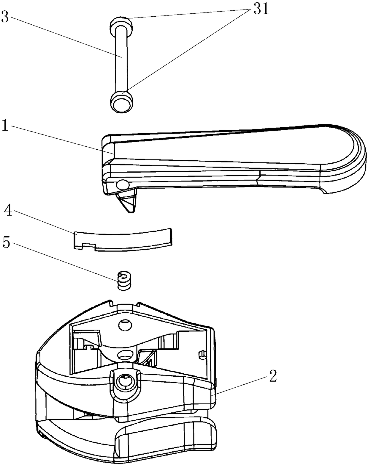
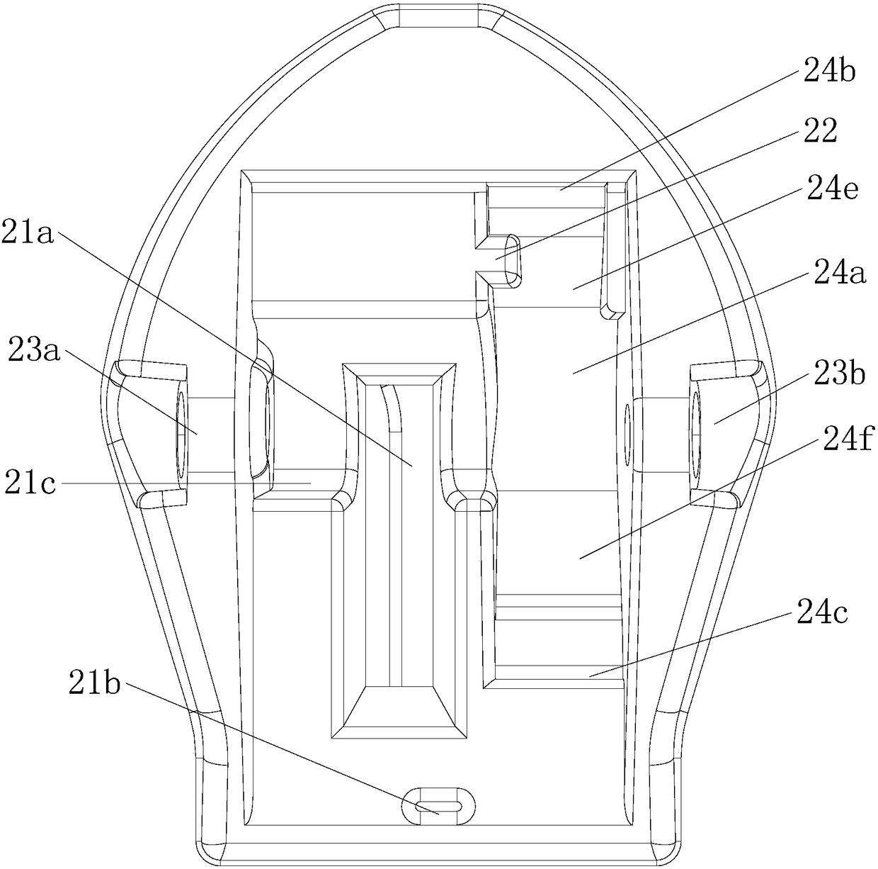
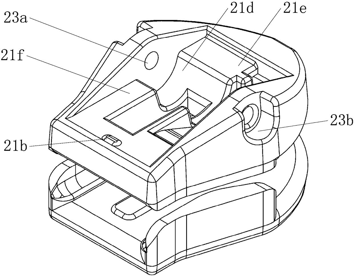
[0038] The invention discloses a shrapnel slider, such as Figure 1-4 As shown, it includes a pull card 1, a slider base 2, a connecting shaft 3, a shrapnel 4 and a spring 5, and the slider base 2 includes an upper wing 25 and a lower wing 26, and upper wings are provided on both sides of the upper wing 25. Two through holes for installing the connecting shaft 3 are provided on the side of the upper wing, including the first through hole 23a and the second through hole 23b, and the upper surface of the upper wing 25 is provided with a front end platform 21e and a rear end platform The two planes of 21f are also provided with a downwardly recessed semicircular concave surface 21 and a downwardly concave arc concave surface 24. The first through hole 23a is arranged on one side of the semicircular concave surface, and the second through hole 23b is ...


PUM


Abstract

The invention discloses an elastic piece slider, and relates to the field of self-locking sliders capable of automatically rebounding. The elastic piece slider comprises a slider base, a puller, a connecting shaft, an elastic piece and a spring, wherein the slider base is provided with a downwards-sunken semicircular concave surface and a downwards-sunken cambered concave surface; the elastic piece is arranged in the cambered concave surface; a circular groove is also formed in the cambered concave surface; the spring is arranged in the circular groove; a rotating part and a locking part are arranged at the top end of the puller, and are adjacent on left and right; the rotating part is provided with a cambered surface; the locking part is provided with a protruded corner higher than the cambered surface; the elastic piece is rectangular and flaky, and is arranged in the cambered concave surface of the slider base; when the puller is arranged flat, the rotating part is pressed against the elastic piece, and the elastic piece is in a slightly bent state to slightly press the spring. According to the elastic piece slider, the puller can automatically rebound to automatically lock a zipper after being pulled by approximately 90 degrees, so that the slider is prevented from sliding when not being used, and the elastic piece can be prevented from being separated from the slider even when being damaged.

Description

technical field [0001] The invention relates to the field of zippers, in particular to a slider that can automatically rebound and has a self-locking function. Background technique [0002] In the slider for zipper with automatic locking device, the hook structure is usually used to realize the function of automatic rebound of the card. Patent 103220932A discloses a slider for zipper with automatic braking device. The slide fastener slider of the stopper device includes: a main body formed with a fastener element guide passage through which the fastener elements can penetrate; It has a locking claw protruding from a locking window hole formed in the above-mentioned main body into the above-mentioned chain element guide passage; a force applying part that applies force to the above-mentioned locking member so that the above-mentioned locking claw is released from the above-mentioned locking window hole Protruding into the above-mentioned chain element guide passage, the slid...

Claims


Application Information

Patent Timeline
Patent Type & Authority Patents(China)
IPC IPC(8): A44B19/30
CPCA44B19/30
Inventor 熊梓仁吕宗坚丘巍曾健安吴富康
Owner IDEAL FASTENER GUANG DONG IND LTD
Learn More