Cam clamping device

A technology of clamping device and wedge, applied in the direction of workpiece clamping device, manufacturing tools, etc., can solve the problems of too long force arm of the pressure plate, large geometric size, and torque generation

Active Publication Date: 2017-09-15
SHANGHAI MOTOR VEHICLE INSPECTION CERTIFICATION & TECH INNOVATION CENT CO LTD
View PDF6 Cites 0 Cited by
  • Summary
  • Abstract
  • Description
  • Claims
  • Application Information

AI Technical Summary

Problems solved by technology

[0002] The clamping device is used for clamping between two parts. For the traditional clamping device, for the clamping between two parts at 90° to the direction of force (clamping operation in the form of perforation), the clamping The direction of force makes it impossible to reach into the wrench type tool
Moreover, the geometric dimensions of the two parts are relatively large, especially for flat parts, and hands or tools cannot reach into the clamping position.
[0003] For example, the oblique wedge clamping device that applies force to the slide block through the inclined roller to drive the pressure plate on the slide block to move up and down to clamp the workpiece is only suitable for small workpieces, and its disadvantage is that the force arm of the pressure plate should not exceed long
For the double wedge clamping device, which utilizes the movement of the two jacks on the double wedge along the inclined plane to increase the axial distance between them to clamp the parts, the disadvantage is that the clamping force is not on a straight line, thus generating torque

Method used


Image

  • Cam clamping device

Examples


Embodiment Construction

[0014] The above-mentioned features and advantages of the present invention can be better understood after reading the detailed description of the embodiments of the present disclosure in conjunction with the following drawings. In the drawings, components are not necessarily drawn to scale, and components with similar related properties or characteristics may have the same or similar reference numerals.

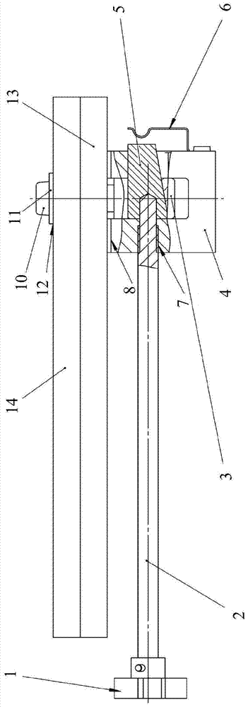
[0015] figure 1 The structure of a preferred embodiment of the wedge clamping device of the present invention is shown. See figure 1 , the wedge clamping device of this embodiment includes a handle 1, a wedge 5, a fixing frame 4, a fixing piece 3, and a stud 2, wherein the handle 1 is installed on one end of the stud 2, and the other end of the stud 2 passes through the fixing frame The threaded hole 7 of 3 enters the wedge hole of the wedge 5, the fixing part 3 is installed in the long groove of the fixing frame 4, the fixing part 3 has an oblique square hole, and the obl...


PUM


Abstract

The invention discloses an oblique wedge clamping device, which has light and novel design, simple and practical principle, large clamping contact surface, light total weight, few components and good processability. The technical solution is: the device includes a handle, a wedge, a fixing frame, a fixing piece, and a stud, wherein the handle is installed at one end of the stud, and the other end of the stud enters the wedge hole of the wedge through the threaded hole of the fixing frame , the fixing part is installed in the long groove of the fixing frame, the fixing part has a sloped square hole, the oblique wedge is installed in the oblique square hole of the fixing part, and the oblique surface of the oblique wedge and the oblique surface of the oblique square hole of the fixing part fit together.

Description

technical field [0001] The invention relates to a clamping device, in particular to a wedge clamping device. Background technique [0002] The clamping device is used for clamping between two parts. For the traditional clamping device, for the clamping between two parts at 90° to the direction of force (clamping operation in the form of perforation), the clamping The direction of force prevents access to tools such as wrenches. Moreover, the geometric dimensions of the two parts are relatively large, especially the flat parts, so that hands or tools cannot reach the clamping position. [0003] For example, the oblique wedge clamping device that applies force to the slide block through the inclined roller to drive the pressure plate on the slide block to move up and down to clamp the workpiece is only suitable for small workpieces, and its disadvantage is that the force arm of the pressure plate should not exceed long. As for the wedge clamping device that tightens the bol...

Claims


Application Information

Patent Timeline
Patent Type & Authority Patents(China)
IPC IPC(8): B25B11/02
Inventor 丁珺
Owner SHANGHAI MOTOR VEHICLE INSPECTION CERTIFICATION & TECH INNOVATION CENT CO LTD
Why Eureka
Try Eureka