A garbage conveying device

A technology of garbage conveying and garbage hopper, applied in the field of garbage conveying device, can solve the problems of insufficient secondary energy recovery, environmental pollution, complex structure, etc., and achieve the effect of improving work efficiency, saving investment and space occupation, and having strong mobility.

Active Publication Date: 2018-11-27
泰州市海星环保设备安装有限公司
View PDF7 Cites 0 Cited by
  • Summary
  • Abstract
  • Description
  • Claims
  • Application Information

AI Technical Summary

Problems solved by technology

Especially when using a vehicle with a mechanical arm for transportation, in addition to the environmental pollution caused by the exhaust gas emitted by the vehicle itself, there are also problems such as large energy consumption, complicated structure, and insufficient secondary energy recovery.

Method used


Image

  • A garbage conveying device
  • A garbage conveying device
  • A garbage conveying device

Examples


Embodiment 1

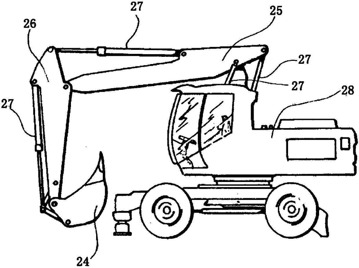
[0021] Such as figure 1 A kind of garbage conveying device shown, comprises car body 28, garbage hopper 24, first mechanical arm 25, second mechanical arm 26, hydraulic rod 27 and engine system, described car body 28, first mechanical arm 25, the first mechanical arm The two mechanical arms 26 and the garbage bucket 24 are sequentially hingedly connected; a plurality of said hydraulic rods 27 are successively installed between the vehicle body 28 and the first mechanical arm 25, between the first mechanical arm 25 and the second mechanical arm 26, and between the second mechanical arm 25 and the second mechanical arm 26. Between the mechanical arm 26 and the garbage bucket 24 is used to drive the first mechanical arm 25 , the second mechanical arm 26 and the garbage bucket 24 to move; the vehicle body 28 is driven by the engine 2 .

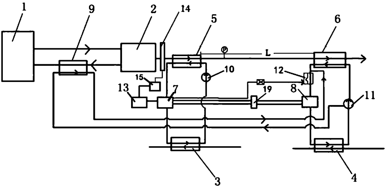
[0022] Such as figure 2 As shown, the engine energy recovery device is used to recover the energy of the exhaust gas of the engine 2, which inc...

Embodiment 2

[0032] Such as figure 1 A kind of garbage conveying device shown, comprises car body 28, garbage hopper 24, first mechanical arm 25, second mechanical arm 26, hydraulic rod 27 and engine system, described car body 28, first mechanical arm 25, the first mechanical arm The two mechanical arms 26 and the garbage bucket 24 are sequentially hingedly connected; a plurality of said hydraulic rods 27 are successively installed between the vehicle body 28 and the first mechanical arm 25, between the first mechanical arm 25 and the second mechanical arm 26, and between the second mechanical arm 25 and the second mechanical arm 26. Between the mechanical arm 26 and the garbage bucket 24 is used to drive the first mechanical arm 25 , the second mechanical arm 26 and the garbage bucket 24 to move; the vehicle body 28 is driven by the engine 2 .

[0033] Such as figure 2As shown, the engine energy recovery device is used to recover the energy of the engine exhaust, which includes a radiat...

Embodiment 3

[0043] Such as figure 1 A kind of garbage conveying device shown, comprises car body 28, garbage hopper 24, first mechanical arm 25, second mechanical arm 26, hydraulic rod 27 and engine system, described car body 28, first mechanical arm 25, the first mechanical arm The two mechanical arms 26 and the garbage bucket 24 are sequentially hingedly connected; a plurality of said hydraulic rods 27 are successively installed between the vehicle body 28 and the first mechanical arm 25, between the first mechanical arm 25 and the second mechanical arm 26, and between the second mechanical arm 25 and the second mechanical arm 26. Between the mechanical arm 26 and the garbage bucket 24 is used to drive the first mechanical arm 25 , the second mechanical arm 26 and the garbage bucket 24 to move; the vehicle body 28 is driven by the engine 2 .

[0044] Such as figure 2 As shown, the engine energy recovery device is used to recover the energy of the engine exhaust, which includes a radiato...


PUM


Abstract

The invention discloses a novel garbage conveying device. The novel garbage conveying device comprises a truck body, a garbage hopper, a first mechanical arm, a second mechanical arm, hydraulic rods and an engine system, wherein the truck body, the first mechanical arm, the second mechanical arm and the garbage hopper are successively articulated with each other; a plurality of hydraulic rods are successively mounted between the truck body and the first mechanical arm, between the first mechanical arm and the second mechanical arm and between the second mechanical arm and the garbage hopper and are used for driving the first mechanical arm, the second mechanical arm and the garbage hopper to act; the truck body is driven by an engine; an engine exhaust energy recycling device is used for recycling energy of the engine exhaust. The novel garbage conveying device is simple and practical in structure, convenient to convey and high in movability; the energy can be recycled, so that the novel garbage conveying device is energy-saving and environmentally-friendly.

Description

technical field [0001] The invention relates to the field of garbage disposal, in particular to a garbage conveying device. Background technique [0002] Garbage conveying is one of the most basic links of garbage disposal. The existing garbage conveying methods generally include belt conveying, mechanical arm conveying, and elevator conveying. But no matter which method is used, the energy saving problem in the transportation process is still an important issue that people are concerned about. Especially when using a vehicle with a mechanical arm for transportation, in addition to the environmental pollution caused by the exhaust gas emitted by the vehicle itself, there are also problems such as large energy consumption, complicated structure, and insufficient secondary energy recovery. Contents of the invention [0003] In view of the above problems, the present invention provides a garbage conveying device. [0004] The object of the present invention adopts following...

Claims


Application Information

Patent Timeline
Patent Type & Authority Patents(China)
IPC IPC(8): F01K23/04F01K23/10F01K13/02B65F3/00
CPCB65F3/00F01K13/02F01K23/04F01K23/065F01K23/10
Inventor 时建华
Owner 泰州市海星环保设备安装有限公司
Why Eureka
Try Eureka