Working fluid output device of temperature control system

A technology of temperature control system and working fluid, which is applied to fixtures, mechanical equipment, etc., can solve the problems of time-consuming and laborious disassembly and assembly of the protective cover, damage to the glass tube of the protective cover, etc., and achieves the effect of safe and convenient disassembly and assembly.

Active Publication Date: 2016-07-20
MPI CORP
View PDF4 Cites 0 Cited by
  • Summary
  • Abstract
  • Description
  • Claims
  • Application Information

AI Technical Summary

Problems solved by technology

However, this kind of working fluid output device also requires the use of tools to disassemble the protective cover. Once the tools are used improperly, the glass tube of the protective cover may be damaged, and the removal of the protective cover is time-consuming and laborious.

Method used


Image

  • Working fluid output device of temperature control system
  • Working fluid output device of temperature control system
  • Working fluid output device of temperature control system

Examples


Embodiment Construction

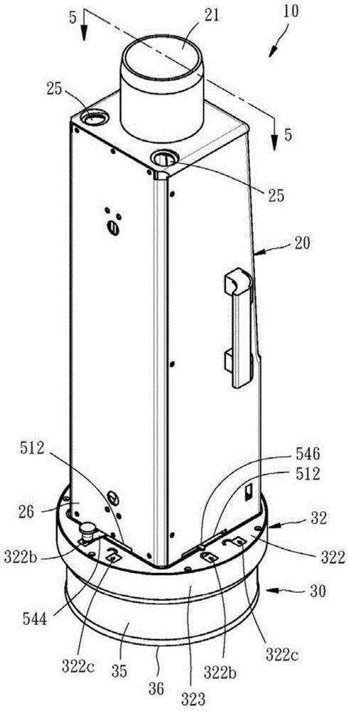
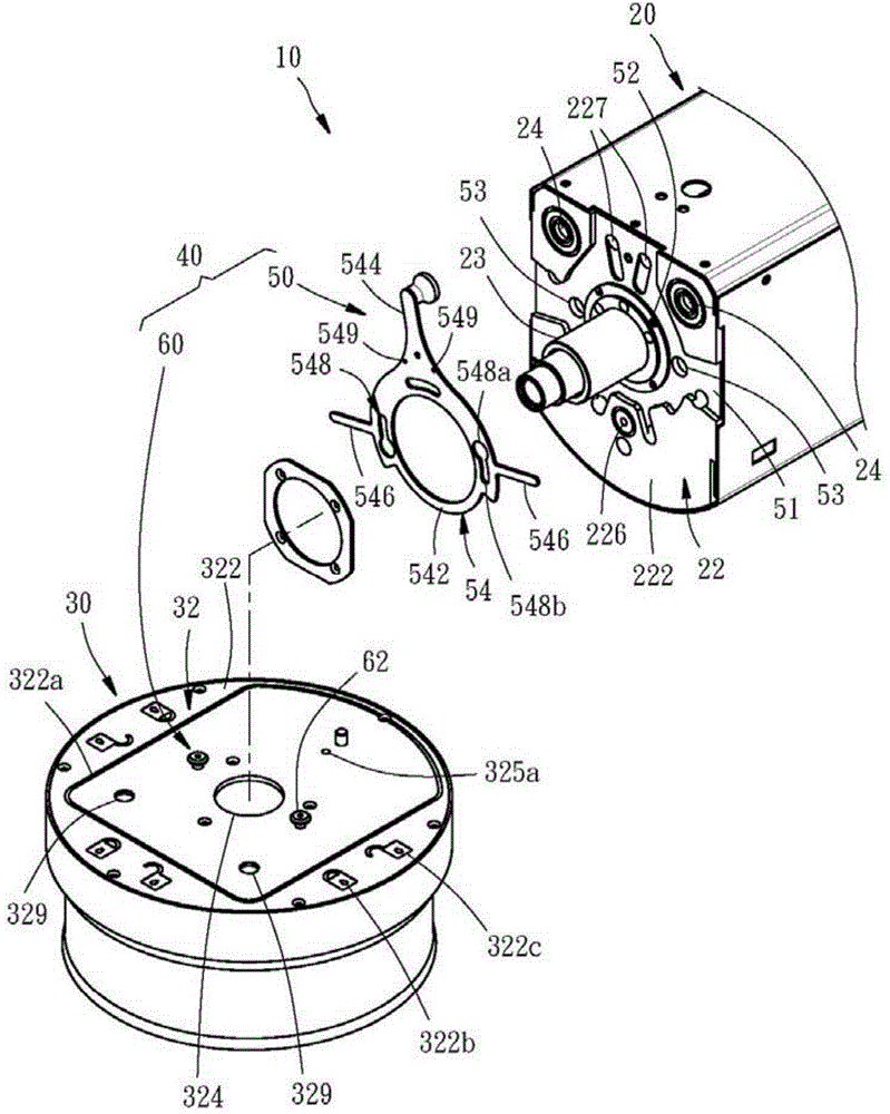
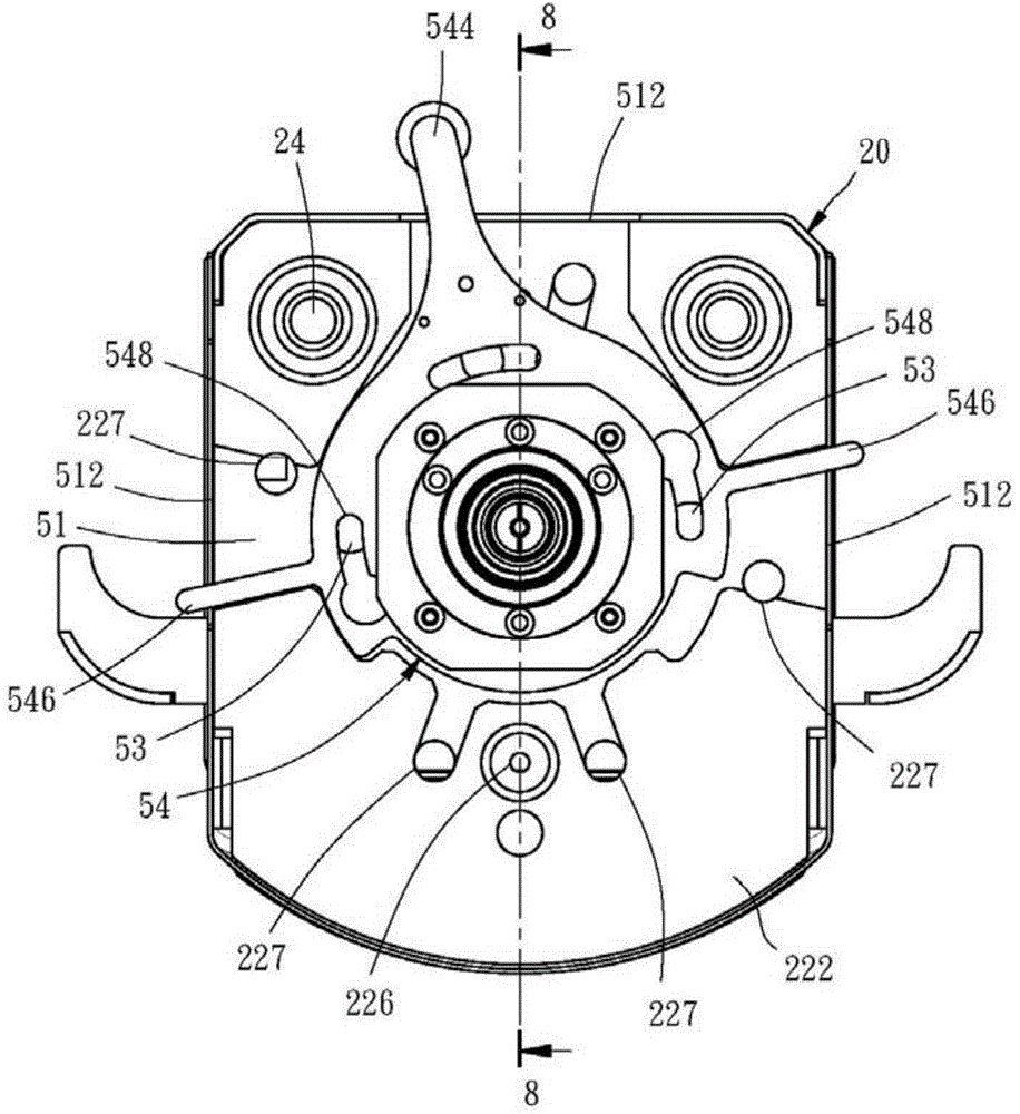
[0036] The detailed structure, characteristics, assembly or usage of the working fluid output device of the temperature control system of the present invention will now be described in detail with reference to the following embodiments and accompanying drawings. However, those skilled in the field of the present invention should be able to understand that these detailed descriptions and the specific examples enumerated for implementing the present invention are only for illustrating the present invention, and are not intended to limit the patent application scope of the present invention.

[0037] The applicant first explains here that in the embodiments and drawings to be described below, the same reference numerals denote the same or similar elements or structural features. Secondly, when it is mentioned that one element is arranged on another element, it means that the aforementioned element is directly arranged on the other element, or that the aforementioned element is ind...


PUM


Abstract

Provided is a working fluid output device of temperature control system. The working fluid output device of temperature control system comprises an output head, a fitting assembly, and a quick-release mechanism. The bottom plate of the output head and a top plate of the fitting component are respectively provided with a mounting surface and a through hole. The quick-release mechanism comprises a first unit and a second unit respectively disposed on the two mounting surfaces. The first unit comprises an operating member which has a positioning portion and is operated by a user to move the positioning portion between a locking position and an unlocking position, and thus allow the first unit and the second unit to be detachably connected, and allow the fitting component to be detachably disposed on the output head by having the two mounting surfaces facing each other and the two through holes communicated with each other. Thus, the fitting component may be quickly, safely, and conveniently mounted and detached.

Description

technical field [0001] The present invention relates to a temperature control system, in particular to a working fluid output device of the temperature control system. Background technique [0002] When testing electronic components or electronic devices (such as chips, integrated circuits, printed circuits, etc.) Whether it can function normally in a certain temperature range. It is conceivable that in the aforementioned testing process, a temperature control system needs to be used to control the temperature of the object under test as accurately as possible to the set temperature. A conventional temperature control system uses a temperature control device (such as a refrigeration and air conditioning device) that can adjust the temperature of the working fluid (liquid or gas) to provide a working fluid at a specific temperature, and uses a working fluid output device to guide the working fluid To the surroundings of a test object to change its temperature. [0003] Ple...

Claims


Application Information

Patent Timeline
Patent Type & Authority Applications(China)
IPC IPC(8): F16B1/02
Inventor 克里斯塔·赫尔格·雅各李岳颖张盈乔
Owner MPI CORP
Why Eureka
Try Eureka