
The connection structure between the pin and the chuck seat of the tire rear inflation device

A technology of an inflatable device and a connection structure, which is applied in the field of the connection structure between the bolt and the chuck seat, and can solve problems such as ground personnel or parts being damaged, the chuck seat falling, and the bolt and the chuck seat being disengaged, so as to prevent falling Effect

Active Publication Date: 2017-04-12
JIANGSU HUAAO RUBBER MACHINERY
View PDF5 Cites 0 Cited by
  • Summary
  • Abstract
  • Description
  • Claims
  • Application Information

AI Technical Summary

Problems solved by technology

[0004] Since the clamping and separation between the bolt and the chuck seat are all realized by the cylinder, in the actual operation process, the bolt often shrinks suddenly when the cylinder is at a high position due to the failure of the solenoid valve controlling the cylinder or human misoperation. In turn, the bolt and the chuck seat are suddenly disengaged, causing the chuck seat to fall from a high place, thereby causing damage to ground personnel or parts

Method used


Image

  • The connection structure between the pin and the chuck seat of the tire rear inflation device
  • The connection structure between the pin and the chuck seat of the tire rear inflation device
  • The connection structure between the pin and the chuck seat of the tire rear inflation device

Examples


Embodiment Construction

[0031] Preferred embodiments of the present invention will be described in detail below in conjunction with the accompanying drawings.

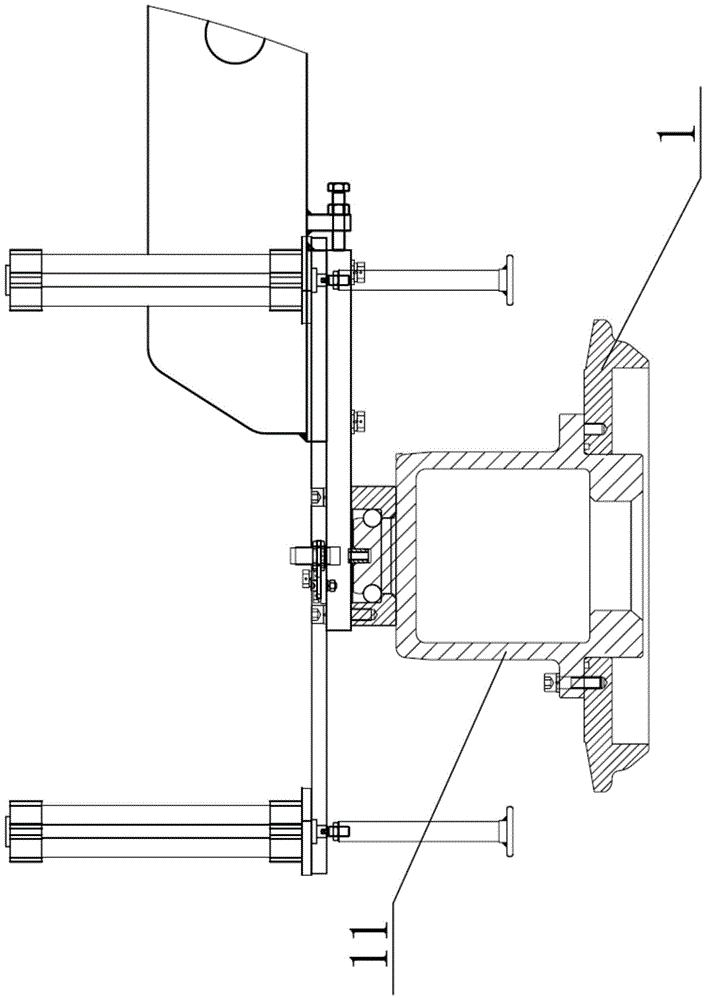
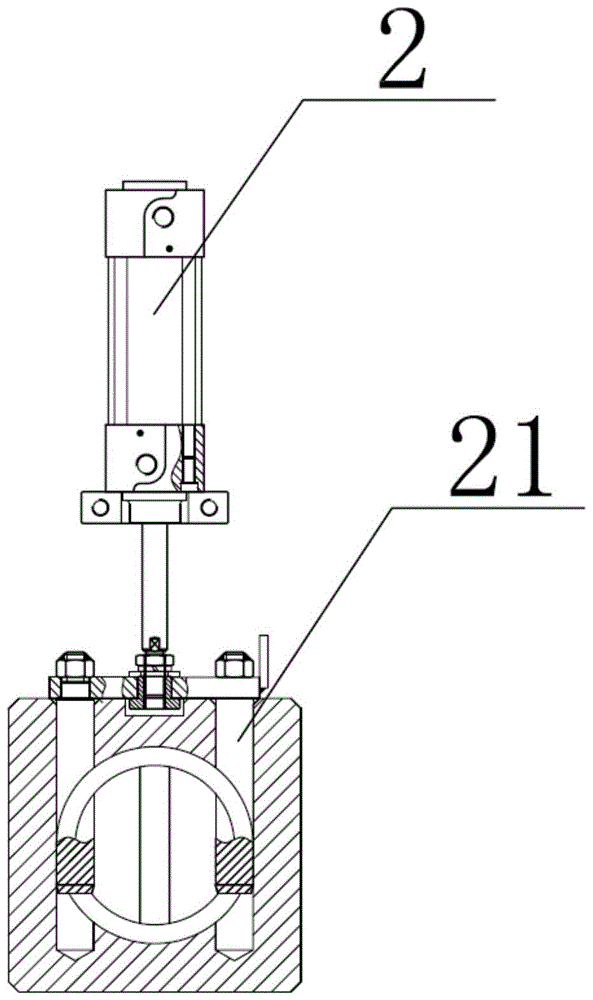
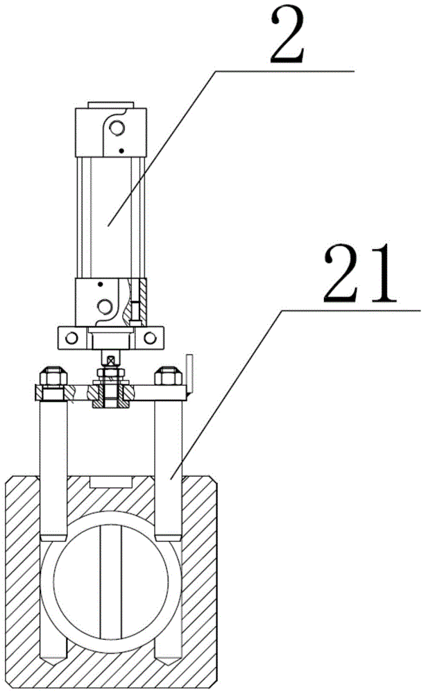
[0032] In order to achieve the purpose of the present invention, as Figure 4-8 As shown, in some embodiments of the connection structure between the latch and the chuck seat of the tire rear inflation device of the present invention, the latch 21 and the chuck seat 11 are detachably connected by a known method such as clamping, and the latch 21 is connected by Cylinder 2 drives. The connection mode of this plug pin and the chuck seat is generally used in some tire rear inflation devices, and the present invention uses it as an example to describe the improvement of the present invention together. Of course, for the tire rear inflation device, there may be some differences in the connection between the plug pin and the chuck seat, and those skilled in the art can apply the improvement of the present invention to these tire rear inflation dev...


PUM


Abstract

The invention discloses a connecting structure of a plug pin and a chuck seat of a tire rear inflation device. The plug pin is connected with the chuck seat detachably; a pressing-downwards element is clamped on the plug pin; an elastic element is arranged between the press-downwards element and the chuck seat. Compared with the prior art, the connecting structure effectively utilizes the chuck seat self as well as the combined action of the press-downwards element and the elastic element which are mounted on the chuck seat, and thus, the chuck seat is effectively positioned at a high position and the chuck seat also can be positioned on the plug pin under the condition that a cylinder is in failure or is artificially and falsely operated, so that the chuck seat is effectively prevented from falling off and that ground service staff and parts are not damaged is ensured.

Description

technical field [0001] The invention relates to a chuck seat structure of a tire rear inflation device, in particular to a connection structure between a plug pin and a chuck seat of a tire rear inflation device. Background technique [0002] In the current tire rear inflation device, chuck and chuck seat are necessary components on it. Such as figure 1 As shown, the chuck 11 is fixedly installed on the bottom of the chuck base 1 . [0003] When the tire rear inflation device is working, the chuck seat is driven by the cylinder to realize two states of closing and disengaging. figure 2 It shows the closed state of the chuck seat. When the chuck seat 1 is at a high position, the cylinder 2 drives the latch 21 forward, and the latch 21 enters the top of the chuck seat 1. Through the engagement with the top of the chuck seat 1, the chuck seat 1 Positioning to prevent the chuck seat 1 from falling when it is in a high position. image 3 It shows the disengaged state of the ...

Claims


Application Information

Patent Timeline
Patent Type & Authority Patents(China)
IPC IPC(8): B29C35/16B29L30/00
Inventor 黄桂强厉福陆
Owner JIANGSU HUAAO RUBBER MACHINERY
Learn More