Concrete bridge supporting column construction operation method

A technology of concrete and supporting columns, which is applied in the direction of bridges, bridge parts, bridge construction, etc., can solve the problems that affect the safe construction process of the construction operation team, do not have the characteristics of automatic splitting of molds, and do not have the characteristics of movement, so as to reduce the Difficulty of construction work, fast disassembly and assembly, and fast clamping effects

Inactive Publication Date: 2021-03-09
潘林妃
View PDF0 Cites 0 Cited by
  • Summary
  • Abstract
  • Description
  • Claims
  • Application Information

AI Technical Summary

Problems solved by technology

[0003] 1. Usually the height of the bridge support column is high, and the disassembly of the uppermost mold belongs to high-altitude operations. High-altitude operations are very dangerous for workers, and it is not conducive to the rapid disassembly of the mold, and the common bridge support column construction equipment has molds integrated The structure does not have the function of automatically splitting the mold, which in turn affects the safety of the entire construction team and the construction process;
[0004] 2. Common bridge support column construction equipment does not have the characteristics of mobility, and the applicable environment is limited, which affects the use of the equipment and easily causes the phenomenon of idle resources

Method used


Image

  • Concrete bridge supporting column construction operation method
  • Concrete bridge supporting column construction operation method
  • Concrete bridge supporting column construction operation method

Examples


Embodiment Construction

[0031] In order to make the technical means, creative features, goals and effects achieved by the present invention easy to understand, the present invention will be further described below in conjunction with specific illustrations. It should be noted that, in the case of no conflict, the embodiments in the present application and the features in the embodiments can be combined with each other.

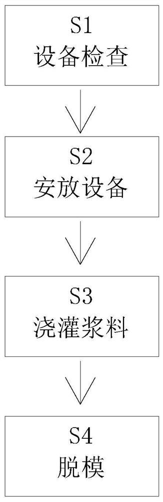
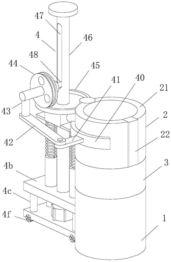
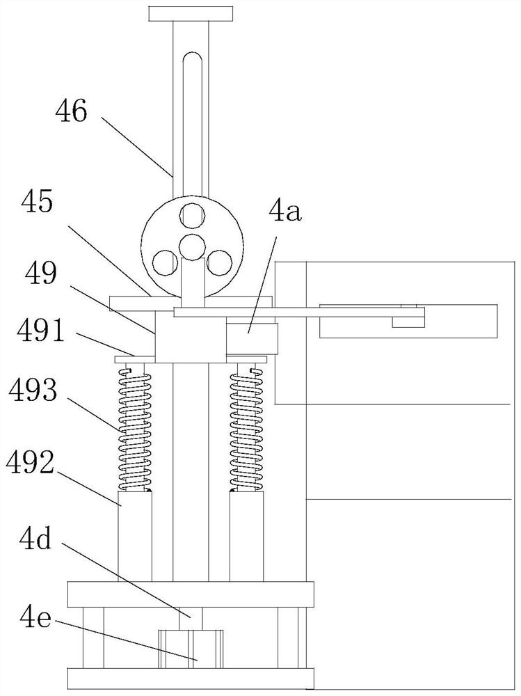
[0032] Such as Figure 1 to Figure 7 Shown, a kind of concrete bridge support column construction operation method, this concrete bridge support column construction operation method adopts following equipment to carry out construction, and this equipment comprises lower mold 1, upper mold 2, connector 3 and demoulding device 4, described The lower end of the lower mold 1 is installed on the existing ground, the top of the lower mold 1 is provided with an upper mold 2, a connecting piece 3 is installed between the upper end of the lower mold 1 and the lower end of the upper mold 2, an...


PUM


Abstract

The invention provides a concrete bridge supporting column construction operation method. The concrete bridge supporting column construction operation method adopts the following equipment for construction, the equipment comprises a lower mold, an upper mold, a connecting piece and a demolding device, the lower end of the lower mold is installed on the existing ground, the upper mold is arranged above the lower mold, the connecting piece is mounted between the upper end of the lower mold and the lower end of the upper mold, and the demolding device is arranged at the left side of the upper mold. Through mutual cooperation of a first motor, a rotating shaft, a rotating rod and a rolling wheel, the rolling wheel can synchronously rotate on the edge of a disc, the rolling wheel, an L-shaped column, smf a hinge rod and a lug base are matched with one another, so the lug base pulls the arc-shaped block to disassemble the upper mold, the function of rapidly disassembling the upper mold can be achieved without manual work, and then the efficiency of construction operation of the concrete bridge supporting rod and the safety degree of the construction process can be improved.

Description

technical field [0001] The invention relates to the field of bridge construction, in particular to a construction operation method for concrete bridge support columns. Background technique [0002] Bridges generally refer to structures erected on rivers, lakes, and seas to allow vehicles and pedestrians to pass smoothly. In order to adapt to the modern high-speed development of the transportation industry, bridges are also extended to cross mountains, poor geology, or meet other traffic needs to make traffic more convenient. Bridges are generally composed of superstructure, substructure, supports and auxiliary structures. The superstructure is also called bridge span structure, which is the main structure for crossing obstacles; the substructure includes abutments, piers and foundations; The force transmission device installed at the supporting place between the span structure and the bridge pier or abutment; the auxiliary structures refer to the bridge head board, conical s...

Claims


Application Information

Patent Timeline
Patent Type & Authority Applications(China)
IPC IPC(8): E01D21/00E01D19/02
CPCE01D19/02E01D21/00
Inventor 潘林妃
Owner 潘林妃
Why Eureka
Try Eureka