Vehicle Lamps

A technology for lamps and vehicles, applied in the direction of headlights, road vehicles, vehicle parts, etc., can solve the problems of inability to fully ensure brightness, increase in brightness, and inability to fully increase maximum luminosity, to ensure front visibility and improve maximum luminosity. Effect

Active Publication Date: 2019-04-23
KOITO MFG CO LTD
View PDF7 Cites 0 Cited by
  • Summary
  • Abstract
  • Description
  • Claims
  • Application Information

AI Technical Summary

Problems solved by technology

[0006] When a pair of left and right light distribution patterns are integrally formed using such a vehicle lamp, if the two are partially overlapped, the brightness of the overlapping portion can be increased, but the maximum luminosity cannot be sufficiently increased.
In addition, in the case where a pair of left and right light distribution patterns are formed separately, it is impossible to sufficiently ensure the brightness of the side end portions of the respective light distribution patterns that are close to the centers of the two light distribution patterns.
Therefore, there is still room for improvement in fully improving the front visibility of the driver of the vehicle

Method used


Image

  • Vehicle Lamps
  • Vehicle Lamps
  • Vehicle Lamps

Examples


Embodiment Construction

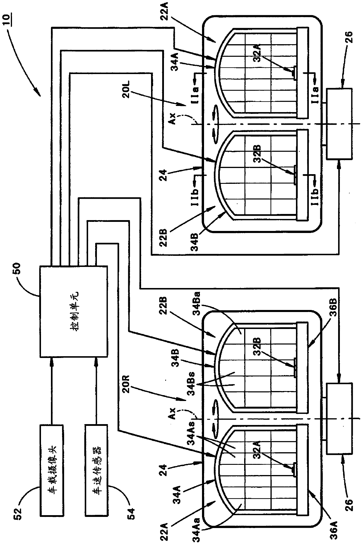
[0060] figure 1 It is a front view showing a vehicle lamp 10 according to an embodiment of the present invention.

[0061] As shown in the figure, the vehicle lamp 10 according to this embodiment includes: a pair of left and right lamp units 20L, 20R; a control unit 50 ; an on-vehicle camera 52 for capturing a scene ahead of the vehicle; and a vehicle speed sensor 54 .

[0062]The left and right pair of lamp units 20L and 20R are lamp units arranged on the left and right sides of the front end of the vehicle, and have a bilaterally symmetrical structure. Each lamp unit 20L, 20R is housed in a lamp chamber formed by a lamp body and a translucent cover which are not shown.

[0063] Each lamp assembly 20L, 20R includes: first and second lamp units 22A, 22B arranged side by side; a support frame 24 for supporting them; The rotation mechanism 26 that rotates the vertical axis Ax in the right and left direction.

[0064] A signal of image data captured by an on-vehicle camera 52 ...


PUM


Abstract

Disclosed is a vehicle lamp a pair of lamp modules configured to irradiate light to form a pair of left and right light distribution patterns. Each of the lamp modules includes first and second lamp units. Further, irradiation light from the first lamp unit forms a first light distribution pattern having a vertically extending cutoff line at a center side of a pair of left and right distribution patterns, and irradiation light from the second lamp unit forms a second light distribution pattern near the cutoff line. The second light distribution pattern is smaller and brighter than the first light distribution pattern.

Description

technical field [0001] The present invention relates to a lamp for a vehicle, which forms a pair of left and right light distribution patterns using irradiation light from a pair of lamp assemblies. Background technique [0002] Conventionally, as a structure of a vehicle lamp, it is known to form a pair of left and right light distribution patterns using irradiation light from a pair of lamp units. [0003] As such a vehicular lamp, "Patent Document 1" describes a vehicular lamp in which each lamp unit is rotatable in the left-right direction. [0004] Patent Document 1: (Japanese) Unexamined Patent Publication No. 2010-140661 [0005] By employing the vehicular lamp described in the aforementioned "Patent Document 1", a pair of left and right light distribution patterns can be formed integrally or separately. [0006] When a pair of left and right light distribution patterns are integrally formed in such a vehicle lamp, if the two are partially overlapped, the luminance ...

Claims


Application Information

Patent Timeline
Patent Type & Authority Patents(China)
IPC IPC(8): F21S41/692F21V14/08F21W102/13F21W107/10
CPCF21V14/04F21S41/32F21W2102/00B60Q1/143B60Q2300/056B60Q2300/112B60Q2300/322B60Q2300/332B60Q2300/41B60Q2300/42F21S41/148F21S41/16F21S41/176F21S41/657F21S41/663B60Q1/08B60Q2300/32
Inventor 望月光之
Owner KOITO MFG CO LTD
Why Eureka
Try Eureka