
Vehicle headlamp and control method of vehicle headlamp

A technology for headlights and vehicles, applied to vehicle components, optical signals, signal devices, etc., can solve the problems of pedestrians 3a-3c dazzling, visibility changes, number of parts, increase in vehicle weight, etc. Visibility, reduce glare effect

Pending Publication Date: 2020-09-22
KOITO MFG CO LTD +1
View PDF5 Cites 2 Cited by
  • Summary
  • Abstract
  • Description
  • Claims
  • Application Information

AI Technical Summary

Problems solved by technology

In particular, the pedestrians 3a-3c located 10-30m in front of the vehicle 1 are located near the vehicle 1, so the light irradiated from the high beam 2 to the height of the upper body and the face is stronger, giving pedestrians 3a-3c near the vehicle 1 3c brings stronger dazzle
[0006] However, even if the pedestrians 3a-3g are to be prevented from being dazzled similarly to the vehicle in front, the pedestrians 3a-3g themselves do not emit light and their visibility changes greatly due to clothing and the surrounding environment, so it is difficult to communicate with the vehicle in front. The same image recognition based detection
In order to detect the pedestrians 3a to 3g, for example, a method of irradiating infrared rays to the front of the vehicle 1 to capture an infrared image is conceivable, but it is difficult to reliably recognize only the pedestrians 3a to 3g from various surrounding environments.
In addition, the identification of the vehicle ahead requires the use of an infrared irradiator and an infrared camera separately, so there is a problem that the number of parts and the weight of the vehicle increase

Method used


Image

  • Vehicle headlamp and control method of vehicle headlamp
  • Vehicle headlamp and control method of vehicle headlamp
  • Vehicle headlamp and control method of vehicle headlamp

Examples


no. 1 approach

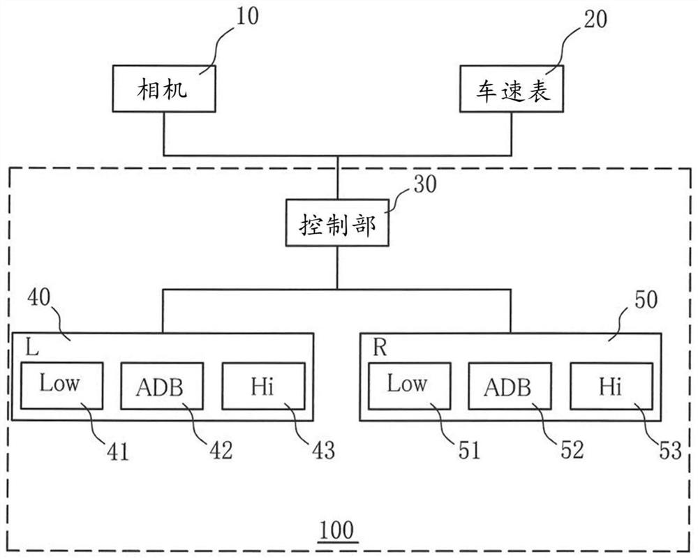
[0053] Hereinafter, embodiments of the present invention will be described in detail with reference to the drawings. The same or equivalent components, components, and processes shown in the drawings are given the same reference numerals, and overlapping descriptions are appropriately omitted. figure 1It is a block diagram schematically showing the configuration of the vehicle headlamp 100 in this embodiment. The vehicle headlamp 100 includes a control unit 30 , a left headlamp 40 , and a right headlamp 50 . In addition, the camera 10 and the speedometer 20 are connected to the control unit 30 , and signals can be communicated between the camera 10 and the speedometer 20 . In addition, the left headlamp 40 and the right headlamp 50 respectively include low beam illuminating units 41 , 51 , ADB illuminating units 42 , 52 , and additional high beam illuminating units 43 , 53 .

[0054] The camera 10 is a device that is attached to the front of the vehicle and captures a front...

no. 2 approach

[0080] Next, use Figure 5 ~ Figure 7 A second embodiment of the present invention will be described. The description of the content overlapping with the first embodiment is omitted. Figure 5 It is a figure which schematically shows the arrangement example of the ADB irradiation part 42,52 and the additional high beam irradiation part 43,53 in this embodiment.

[0081] Such as Figure 5 As shown, in the present embodiment, a left high beam unit LH and a right high beam unit RH are provided, and light emitting diodes are arranged therein. Four light-emitting diodes A1 to D1 of the ADB illuminating unit 42 are arranged laterally on the left side with the high-beam unit LH, and two additional light-emitting diodes of the high-beam illuminating unit 43 are arranged. Likewise, four light-emitting diodes A2 to D2 of the ADB illuminating unit 52 and two additional light-emitting diodes of the high-beam illuminating unit 53 are arranged laterally on the right side with the high be...


PUM


Abstract

Provided are a vehicle headlamp and a method for controlling a vehicle headlamp, whereby glare to a pedestrian and a preceding vehicle can be reduced without providing a special detection means for detecting the pedestrian, and forward visibility can be ensured. This vehicle headlamp is provided with: a low-beam irradiation unit that irradiates light only in lower irradiation region (61,71) belowcut-off line, an additional high-beam irradiation unit that irradiates light with respect to a high-beam irradiation region above the selected irradiation region, and a control unit that controls thelow-beam irradiation unit on the basis of position information indicating the position of a vehicle traveling ahead and travel speed information indicating the speed of the host vehicle. ADB irradiation unit and additional high beam irradiation unit light emission control unit select the upper end of the irradiation region (72) to be in a range of 0.7-1.5 degrees upward from the horizontal direction.

Description

technical field [0001] The present invention relates to a vehicle headlight and a control method for a vehicle headlight arranged in front of a vehicle body, in particular to a vehicle headlight and a control method for a vehicle headlight using light distribution variable high beam technology . Background technique [0002] Conventionally, headlamps for vehicles have been proposed that include a light-emitting element array composed of a plurality of semiconductor light-emitting elements, and use a light source capable of irradiating a plurality of irradiation areas divided in the left-right direction to the upper side than the horizontal line. The light distribution variable high beam (ADB: Adaptive Driving Beam) technology (for example, refer to Patent Document 1). In the vehicle headlamp using such ADB technology, by detecting the vehicle in front, the oncoming vehicle, etc., the light-emitting element array is controlled to not illuminate the area corresponding to its ...

Claims


Application Information

Patent Timeline
Patent Type & Authority Applications(China)
IPC IPC(8): B60Q1/14
CPCB60Q1/1423
Inventor 大盐洋彦山本逸平户高信一后藤亮守屋辉人千千松良
Owner KOITO MFG CO LTD
Learn More