Instrument pointer shaft detector

A detection device and instrument pointer technology, which is applied in angle/taper measurement and other directions, can solve problems such as inaccuracy, large error, and fuzzy detection results, and achieve accurate detection results, elimination of manual operation errors, and rapid detection.

Active Publication Date: 2016-07-20
AEROSPACE HI TECH HLDG GROUP
View PDF6 Cites 6 Cited by
  • Summary
  • Abstract
  • Description
  • Claims
  • Application Information

AI Technical Summary

Problems solved by technology

[0003] The present invention is to solve the problem that the traditional detection pointer shaft is manually placed on the small optical axis, and the non-key parts are detected by using a feeler gauge, and the

Method used


Image

  • Instrument pointer shaft detector
  • Instrument pointer shaft detector
  • Instrument pointer shaft detector

Examples


specific Embodiment approach 1

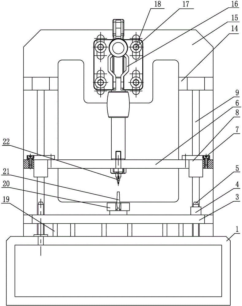
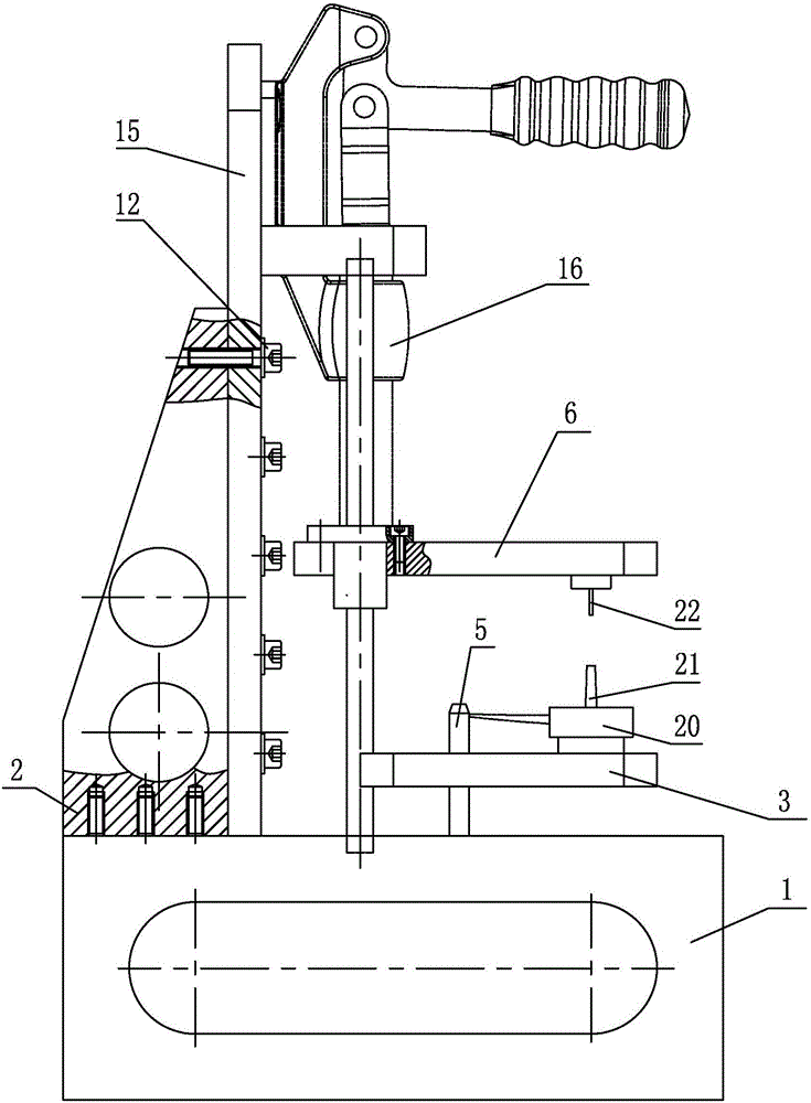
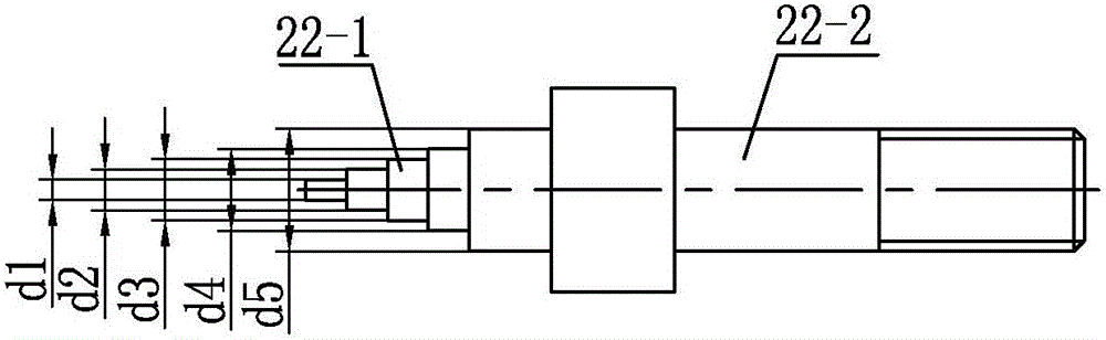
[0012] Specific implementation mode 1: Combination Figure 1-Figure 5 It is explained that an instrument pointer shaft detection device of this embodiment includes a base 1, a pointer board 3, a probe board 6, a vertical board 15, a quick clamp 16, a pointer holder 20, two guide posts 9, two Upper linear bearing 8 and two lower linear bearings 4;

[0013] A vertical plate 15 is fixed on the base 1, two guide posts 9 are arranged side by side and installed vertically on the base 1, a lower linear bearing 4 is installed at the lower end of each guide post 9, and the pointer plate 3 is installed on two lower straight lines On the bearing 4, the pointer plate 3 is equipped with a pointer holder 20 that can rotate in the circumferential direction, the pointer cap of the pointer 21 is mounted on the pointer holder 20, and the two guide posts 9 above the two lower linear bearings 4 are installed Two upper linear bearings 8, the probe card 6 are mounted on the two upper linear bearings ...

specific Embodiment approach 2

[0018] Specific implementation manner two: combination figure 1 It is explained that an instrument pointer shaft detection device of this embodiment further includes two positioning pins 5, two positioning pins 5 and two guide posts 9 are arranged side by side, the positioning pins 5 are installed on the base 1, and the positioning pins 5 pass through the pointer. Plate 3 and the two are in sliding contact. With this arrangement, the positioning pins ensure the parallelism and perpendicularity of the base 1 and the pointer plate 3 and at the same time enable the pointer plate 3 to slide up and down freely. Others are the same as the first embodiment.

specific Embodiment approach 3

[0019] Specific implementation mode three: combination figure 1 It is explained that an instrument pointer shaft detection device of this embodiment further includes a plurality of compression springs 19, and a plurality of compression springs 19 connected to the pointer plate 3 and the base 1 are arranged. The buffer spring provides buffer protection when the pointer shaft 22 is detected. Others are the same as the first or second embodiment.


PUM


Abstract

The invention discloses an instrument pointer shaft detector, relates to shaft detectors and aims at solving the problems that in traditional detection a pointer shaft is placed in a small optical axis manually, a non-key part is detected by a filler gauge, the size of a key part of the pointer shaft is obtained via theoretical reckoning, and further a detection result is fuzzy and inaccurate and has large error. The detector comprises a pedestal, a pointer plate, a probe plate, a vertical plate, a rapid clamp, a pointer fixing seat, two guide posts, two upper linear bearings and two lower linear bearings, wherein the vertical plate is fixedly mounted on the pedestal, the lower end of each guide post is provided with one lower linear bearing, the pointer plate is mounted on the two lower linear bearings, the middle of the pointer plate is provided with the pointer fixing seat, the probe plate is mounted on the two upper linear bearings, the middle of the probe plate is provided with the pointer shaft, the vertical plate over the probe plate is provided with the rapid clamp, and the pressure head end of the rapid clamp abuts against the probe plate. The detector is used for instrument pointer shaft detection.

Description

Technical field [0001] The invention relates to an axle detection device, in particular to an automobile instrument pointer axle detection device. Background technique [0002] When the pointer shaft is detected in the traditional way, the pointer shaft is inserted into the small optical shaft in the detection hole to make the pointer stand upright on the detection end face. After the detection end face rises to a certain position, the feeler gauge is used to detect the gap between the end face and the end face of the pointer cap. Since the pointer is manually placed on the small optical axis, the placement direction and placement force are unstable, and the results obtained are not accurate. Moreover, there is no reference object for comparison, and the inspector cannot visually detect, and can only use the feeler gauge to detect non-critical parts, so as to make theoretical calculations. The results are fuzzy, unclear, and large in error. The detection type is single, and ther...

Claims


Application Information

Patent Timeline
IPC IPC(8): G01B5/25
CPCG01B5/25
Inventor 张志波刘志龙李春龙何琳査森懿韩浩高伟
Owner AEROSPACE HI TECH HLDG GROUP
Why Eureka
Try Eureka