Mandatory Backhaul Structure

A technology of forced return and punch, applied in manufacturing tools, metal processing equipment, stripping devices, etc., can solve the problem of punch not being able to return, and achieve the effect of improving work efficiency

Active Publication Date: 2018-07-20
SHANDONG XIAOYA PRECISE MACHINERY
View PDF6 Cites 0 Cited by
  • Summary
  • Abstract
  • Description
  • Claims
  • Application Information

AI Technical Summary

Problems solved by technology

[0003] The purpose of the present invention is to provide a forced return structure, which controls the stroke of the punch through the hinge, solves the problem that the punch is stuck on the punch fixing plate and cannot return, ensures the normal unloading of the workpiece, and improves work efficiency

Method used


Image

  • Mandatory Backhaul Structure
  • Mandatory Backhaul Structure
  • Mandatory Backhaul Structure

Examples


Embodiment Construction

[0016] The forced backhaul structure of the present invention will be described in detail below with reference to the accompanying drawings.

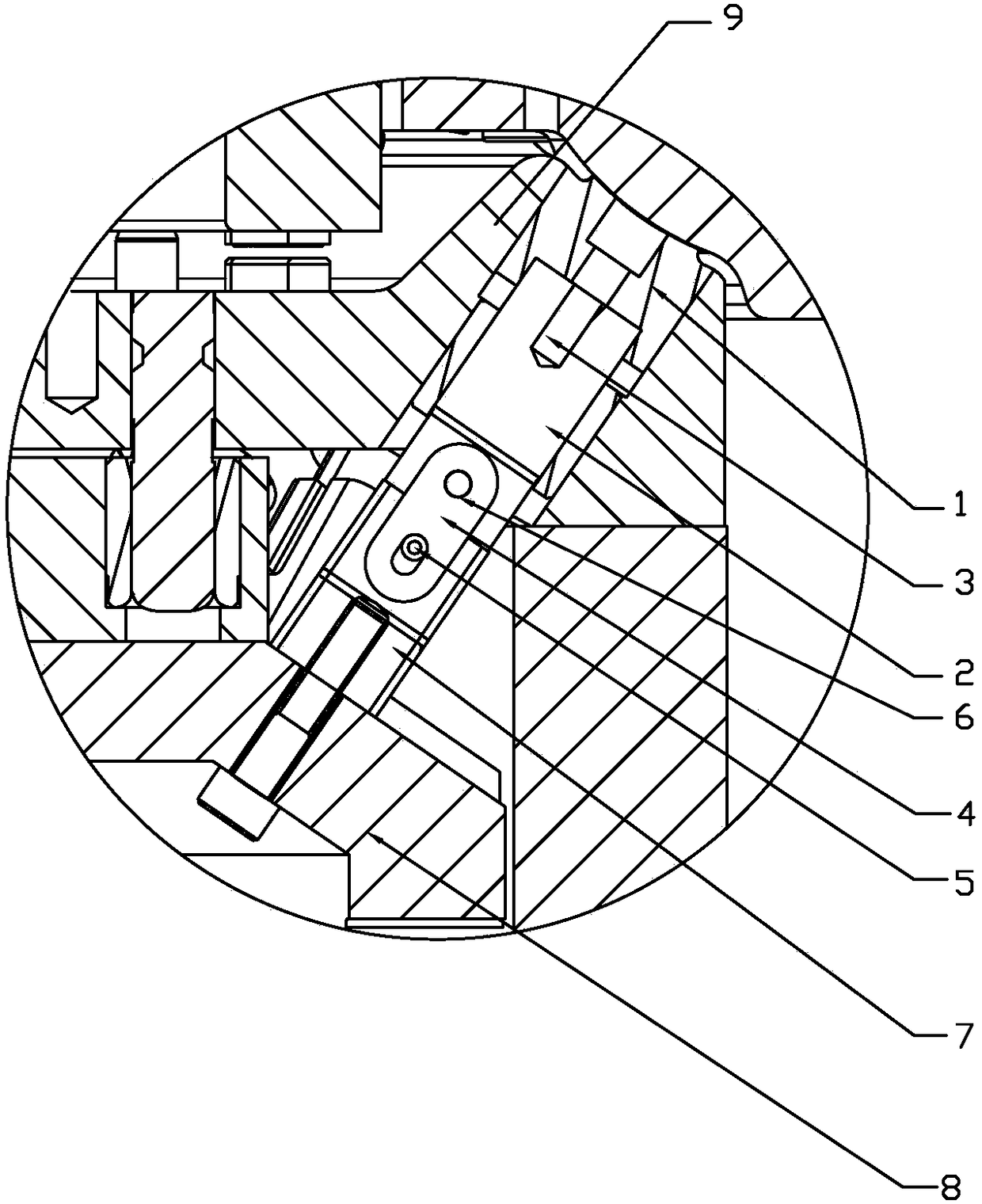
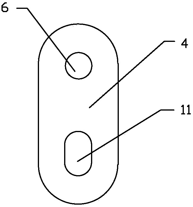
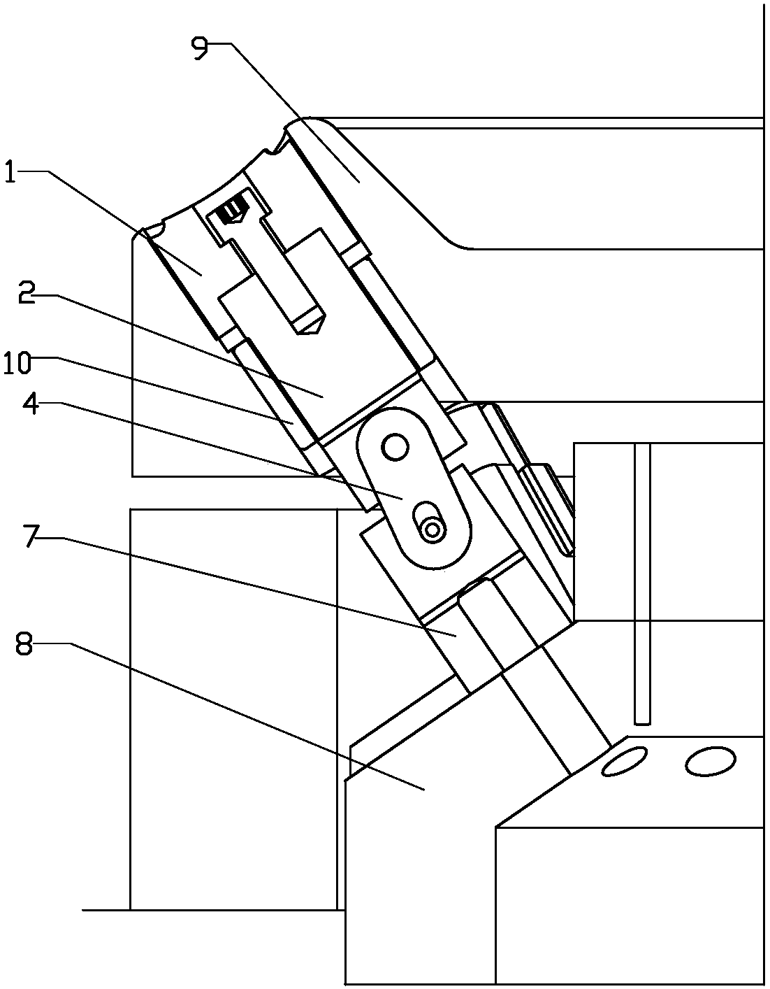
[0017] Such as figure 1 , figure 2 , image 3 , Figure 4 Shown, the forced return structure of the present invention, its structure comprises punch 1, punch fixed rod 2, hinge 4, inclined slide block, inclined slide block fixed plate 8 and punch fixed plate 9, described punch 1 and punch Die fixing bar 2 is connected by screw 3, and described punch fixing bar 2 is connected with inclined slider 7 by hinge 4, and described inclined slider 7 and inclined slider fixing plate 8 are fixed by screw, and one end of described hinge is provided with The mounting hole 6 fixed with the punch fixed rod, the other end of the hinge 4 is provided with a pin hole 11, and a rotating shaft pin 5 is arranged in the described pin hole.

[0018] Described punch fixed plate 9 is provided with the hole of clamping guide sleeve 10, and described guide sl...


PUM


Abstract

The invention discloses a forced returning structure which structurally comprises a male die, a male die fixing rod, a hinge, an inclined sliding block, an inclined sliding block fixing plate and a male die fixing plate. The male die and the male die fixing rod are connected through a screw. The male die fixing rod and the inclined sliding block are connected through the hinge. The inclined sliding block and the inclined sliding block fixing plate are fixed through a screw. One end of the hinge is provided with an installation hole fixed with the male die fixing rod. The other end of the hinge is provided with a pin hole. A rotating shaft pin is arranged in the pin hole. By means of the structure, the stroke of the male die is controlled through the hinge, the problem that the male die is clamped to the male die fixing plate and cannot return is solved, normal discharging of workpieces is ensured, and the working efficiency is improved.

Description

technical field [0001] The invention relates to a peeling device, in particular to a forced return structure. Background technique [0002] When the mold is working, the punch fixing rod slides along the slope of the inclined slider, and the spring overcomes the resistance of the workpiece when it returns. In the work, there are often problems that the punch cannot return due to excessive resistance, and the workpiece is stuck on the punch and cannot be unloaded. Contents of the invention [0003] The purpose of the present invention is to provide a forced return structure, which controls the stroke of the punch through the hinge, solves the problem that the punch is stuck on the punch fixing plate and cannot return, ensures the normal unloading of the workpiece, and improves work efficiency. [0004] The technical scheme adopted by the present invention to solve its technical problems is: forced return structure, including punch, punch fixing rod, hinge, inclined slider,...

Claims


Application Information

Patent Timeline
Patent Type & Authority Patents(China)
IPC IPC(8): B21D37/10B21D45/08
CPCB21D37/10B21D45/006B21D45/08
Inventor 荣盼盼刘健宋治强
Owner SHANDONG XIAOYA PRECISE MACHINERY
Why Eureka
Try Eureka