A bottom ring tension bolt disassembly lift mobile hydraulic trolley

A tension bolt, mobile technology, applied in the field of bottom ring tension bolt disassembly and lifting mobile hydraulic trolley, can solve the problems of bolt and tensioner thread damage, large labor consumption, difficulty in bolt disassembly and assembly, etc., to improve Dismantling efficiency, reducing labor intensity, and high efficiency of disassembly and assembly

Active Publication Date: 2017-09-29
STATE GRID CORP OF CHINA +2
View PDF7 Cites 0 Cited by
  • Summary
  • Abstract
  • Description
  • Claims
  • Application Information

AI Technical Summary

Problems solved by technology

However, when the bottom ring is removed, it is difficult to remove it due to the high position of the bottom ring bolts
The current method usually requires the cooperation of multiple people. One person first lifts the hydraulic tensioner and keeps trying to find the center of the bolt, and then the other person rotates the tensioner and spins the tensioner on the bottom ring bolt to tighten the bolt. Dismantling operations, although this method can remove the bolts, but the work requires a lot of labor, and under high-intensity labor, personnel are prone to fatigue, and work efficiency will become lower and lower. This method also requires workers to have certain skills Work experience can ensure work efficiency and will not damage the threads of bolts and tensioners
At the same time, because the tensioner weighs about 30kg, the bottom ring bolts are located at a higher position, and the number is as many as 104. During the process of aligning the center of the bolts, it takes multiple operations to complete, and it is easy to damage the threads of the bolts and the tensioner
Therefore, the existing technology has problems such as difficult bolt disassembly, low disassembly efficiency, high labor intensity, and easy damage to the thread of the bolt and tensioner.

Method used


Image

  • A bottom ring tension bolt disassembly lift mobile hydraulic trolley
  • A bottom ring tension bolt disassembly lift mobile hydraulic trolley
  • A bottom ring tension bolt disassembly lift mobile hydraulic trolley

Examples


Embodiment

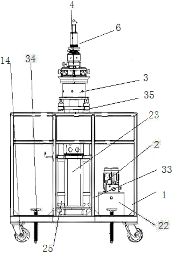
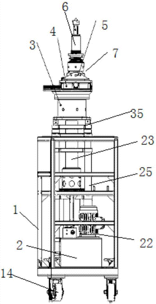
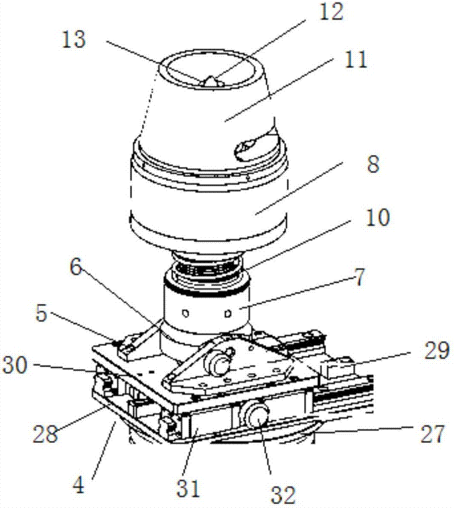
[0023] Embodiment: a bottom ring stretching bolt disassembly lifting mobile hydraulic trolley, constituted as follows figure 1 , figure 2 , image 3 , Figure 4 and Figure 5 As shown, the mobile frame 1 is included, the hydraulic device 2 is arranged in the mobile frame 1, the rotating assembly 3 connected with the mobile frame 1 is arranged above the hydraulic device 2, the displacement assembly 4 is arranged above the rotating assembly 3, and the displacement assembly 4 is provided above The swing assembly, the swing assembly includes a swing shaft support 5 connected with the displacement assembly 4, a swing shaft bolt 6 is connected between the swing shaft support 5, a swing nut 7 is provided at the bottom of the swing shaft bolt 6, and a pull-up nut 7 is provided at the top of the swing nut 7. A compression spring 10 is arranged between the stretcher 8, the stretcher 8 and the screw nut 7, a bridge frame 11 is arranged above the stretcher 8, and a centering cone top ...


PUM


Abstract

The invention discloses a lifting moving type hydraulic trolley for dismounting and mounting of bolts through bottom ring stretching. The lifting moving type hydraulic trolley comprises a moving frame (1), a hydraulic device (2) is arranged in the moving frame (1), a rotating assembly (3) is arranged above the hydraulic device (2), and a displacement assembly (4) is arranged above the rotating assembly (3); a swing assembly is arranged above the displacement assembly (4) and comprises a swing shaft support (5), and a swing shaft bolt (6) is connected between the swing shaft support (5); the lower end of the swing shaft bolt (6) is provided with a screw-up nut (7), a stretching device (8) is arranged at the upper end of the screw-up nut (7), a bridge frame (11) is arranged above the stretching device (8), a centering cone top (12) is arranged in the center of the bridge frame (11), and a laser flashlight (13) is arranged in the centering cone top (12); and moving wheels (14) are arranged at the bottom of the moving frame (1). The lifting moving type hydraulic trolley has the beneficial effects that the bolts can be conveniently dismounted and mounted, the dismounting and mounting efficiency is high, labor intensity is small, and the bolts and stretching device threads are not prone to being damaged.

Description

technical field [0001] The invention relates to a bolt dismounting device, in particular to a bottom ring stretching bolt dismounting lifting mobile hydraulic trolley. Background technique [0002] In order to ensure sufficient sealing performance in existing water turbines, multiple guide vane holes are usually arranged on the bottom ring of the water turbine, and multiple sets of sealing combinations are installed and fixed with bolts. However, when the bottom ring is removed, it is more difficult to remove due to the higher position of the bottom ring bolts. The current method usually requires the cooperation of multiple people. One person first lifts the hydraulic tensioner and keeps trying to find the center of the bolt, and then the other person rotates the tensioner and spins the tensioner on the bottom ring bolt to tighten the bolt. Dismantling operations, although this method can remove the bolts, but the work requires a lot of labor, and under high-intensity labor...

Claims


Application Information

Patent Timeline
Patent Type & Authority Patents(China)
IPC IPC(8): B23P19/06B23P19/10
CPCB23P19/06B23P19/107
Inventor 张仕明卢衍海顾希明邹中林晁新刚
Owner STATE GRID CORP OF CHINA
Why Eureka
Try Eureka