
Automatic intelligent foundation pit inclination measurement system

An inclinometer and intelligent technology, applied in the direction of infrastructure engineering, infrastructure testing, construction, etc., can solve the problem that the foundation pit inclination measuring device cannot automatically measure the inclination, achieve automatic measurement, save engineering time and cost, reduce The effect of measurement error

Active Publication Date: 2016-07-27
SHANGHAI UNIV OF ENG SCI
View PDF4 Cites 10 Cited by
  • Summary
  • Abstract
  • Description
  • Claims
  • Application Information

AI Technical Summary

Problems solved by technology

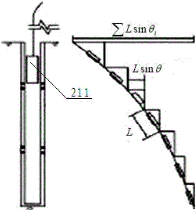
[0004] The automatic intelligent foundation pit inclinometer system of the present invention discloses a new scheme, adopts a brand-new automatic inclinometer system, gets rid of the dependence of traditional inclinometers on labor, and solves the problem that existing foundation pit inclinometer devices cannot automatically measure inclination

Method used


Image

  • Automatic intelligent foundation pit inclination measurement system
  • Automatic intelligent foundation pit inclination measurement system
  • Automatic intelligent foundation pit inclination measurement system

Examples


Embodiment 1

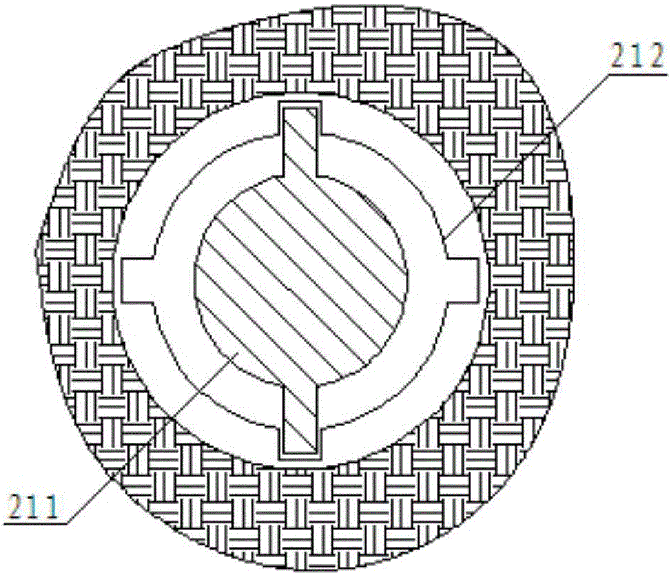
[0021] In order to reduce the adverse effects of external factors on the measurement, the distance measuring disk of this scheme is packaged in the outer shell, the infrared emitting tube and the infrared receiving tube are fixed on the corresponding positions on the inner wall of the outer shell, and the signal cable is wound around the distance measuring circle. A contact friction connection is formed on the end surface of the disk edge, and the inclinometer sensing unit drives the cable to drag the distance measuring disk to rotate under the action of its own gravity. Among them, a group of infrared signal through holes regularly arranged at equal central angles are arranged on the edge of the disc surface of the distance measuring disc along the circumference, and the infrared signal through holes penetrate the disc body of the distance measuring disc along the central axis direction of the distance measuring disc. The infrared emitting tube is arranged at one end of the in...

Embodiment 2

[0023] Such as Figure 5 As shown, another specific implementation of the infrared distance measuring device of this scheme. In order to reduce the adverse effects of external factors on the measurement, the distance measuring disk of this scheme is packaged in the outer shell, and the infrared emitting tube and the infrared receiving tube are fixed on the corresponding positions on the inner wall of the outer shell. The distance-measuring device also includes a distance-measuring driving wheel. The distance-measuring driving wheel and the distance-measuring disc form a transmission connection through a transmission shaft. A group of infrared signal channels regularly arranged at equal central angles are arranged on the edge end surface of the distance-measuring disc along the circumference. The infrared signal through hole penetrates the disc body of the distance measuring disc along the radial direction of the distance measuring disc, the infrared emitting tube is arranged a...


PUM


Abstract

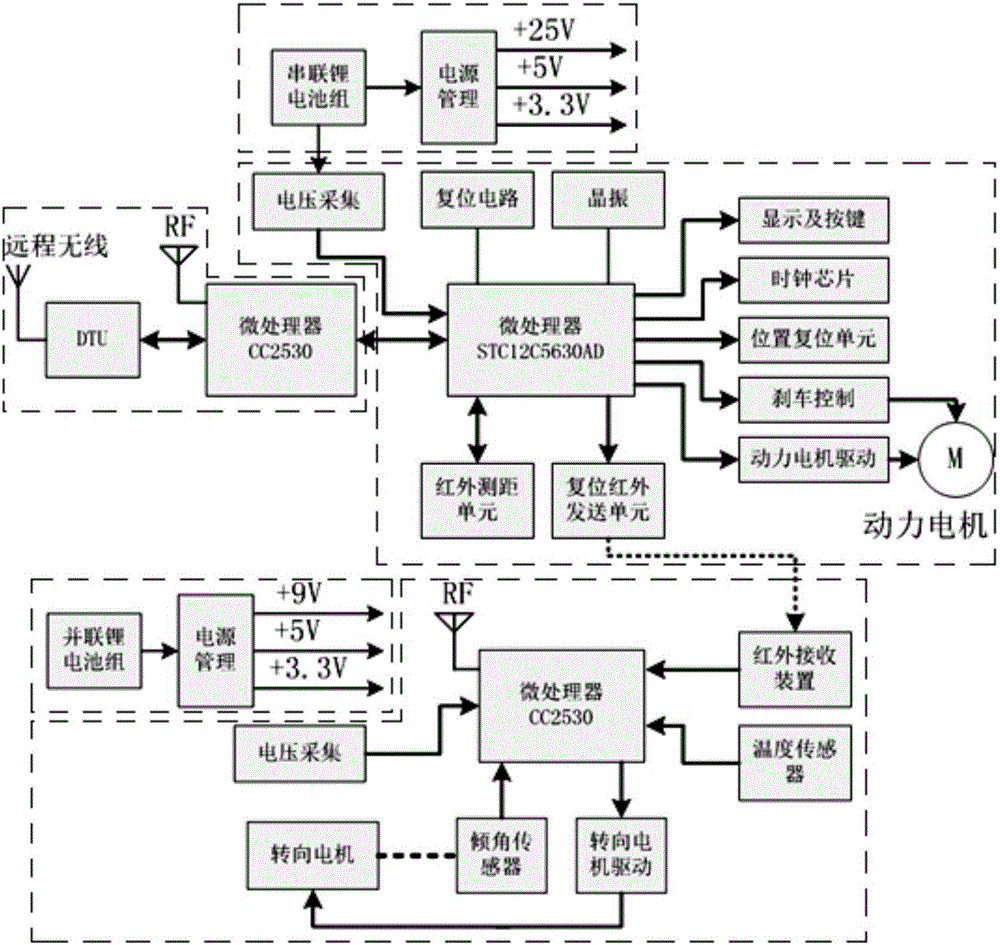
The invention relates to an automatic intelligent foundation pit inclination measurement system. The automatic intelligent foundation pit inclination measurement system comprises an automatic lifting control unit, an inclination measurement sensing unit, a short-range and remote wireless communication unit and power supply units. The automatic lifting control unit comprises a power motor and an automatic lifting control device. The inclination measurement sensing unit comprises an inclination measurement control circuit, an inclination measurement sensor device and a ZigBee single-chip microcomputer. The short-range and remote wireless communication unit comprises a short-range communication ZigBee single-chip microcomputer and a remote communication data transfer unit (DTU) module. The power supply units comprise the ground power supply unit and the inclination measurement sensing power supply unit. According to the automatic intelligent foundation pit inclination measurement system, a brand-new automatic inclination measurement system is adopted, the dependency of a traditional inclinometer on workers is eliminated, and all-weather automatic measurement is achieved; and measurement errors which are caused by human factors can be reduced, the engineering time can be shortened, and the engineering cost can be reduced.

Description

technical field [0001] The invention relates to a foundation pit inclinometer system, in particular to a fully automatic intelligent foundation pit inclination measurement system, which belongs to the field of foundation pit inclination measurement. Background technique [0002] Foundation pit engineering is an ancient and comprehensive geotechnical engineering subject with the characteristics of the times. Slope excavation and simple wooden pile enclosure can be traced back to ancient times. Deep foundation pit projects in modern cities are often located near dense existing buildings, roads and bridges, underground pipelines, subway tunnels or civil air defense projects. Although they are temporary projects, their technical complexity is far greater than that of permanent ones. base structure or superstructure. In the practice of foundation pit engineering, there is often a certain difference between the actual working state of the project and the design working condition,...

Claims


Application Information

Patent Timeline
Patent Type & Authority Applications(China)
IPC IPC(8): E02D33/00
CPCE02D33/00
Inventor 李荣正胡鹏飞陈学军
Owner SHANGHAI UNIV OF ENG SCI
Learn More