
Automatic capping and decapping device

A cap-off, automatic technology, applied in the field of machinery, can solve problems such as capping and capping

Active Publication Date: 2016-08-03
GUANGZHOU INST OF BIOMEDICINE & HEALTH CHINESE ACAD OF SCI
View PDF5 Cites 1 Cited by
  • Summary
  • Abstract
  • Description
  • Claims
  • Application Information

AI Technical Summary

Problems solved by technology

[0004] The present invention aims to overcome the defects of the prior art that caps cannot be added and removed repeatedly in a small space and aseptic environment, improve the adaptability of the capping and removing device, and provide an automatic capping and removing device

Method used


Image

  • Automatic capping and decapping device
  • Automatic capping and decapping device
  • Automatic capping and decapping device

Examples


Embodiment Construction

[0019] In order to make the objectives, technical solutions and advantages of the present invention clearer, the following further describes the present invention in detail with reference to the accompanying drawings and specific embodiments. It should be understood that the specific embodiments described here are only used to explain the present invention, but not to limit the present invention.

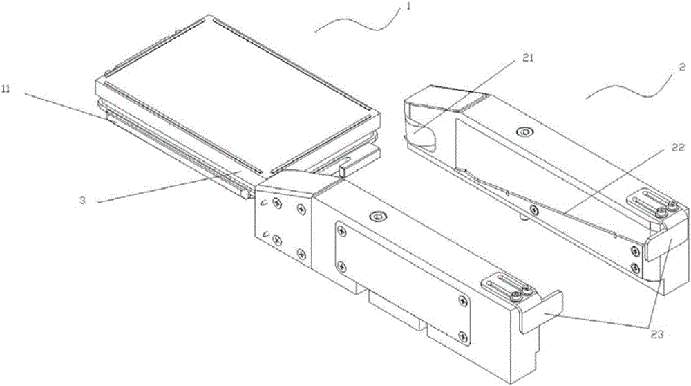
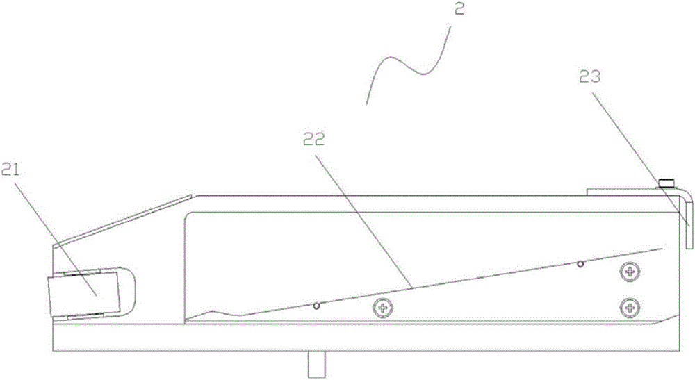
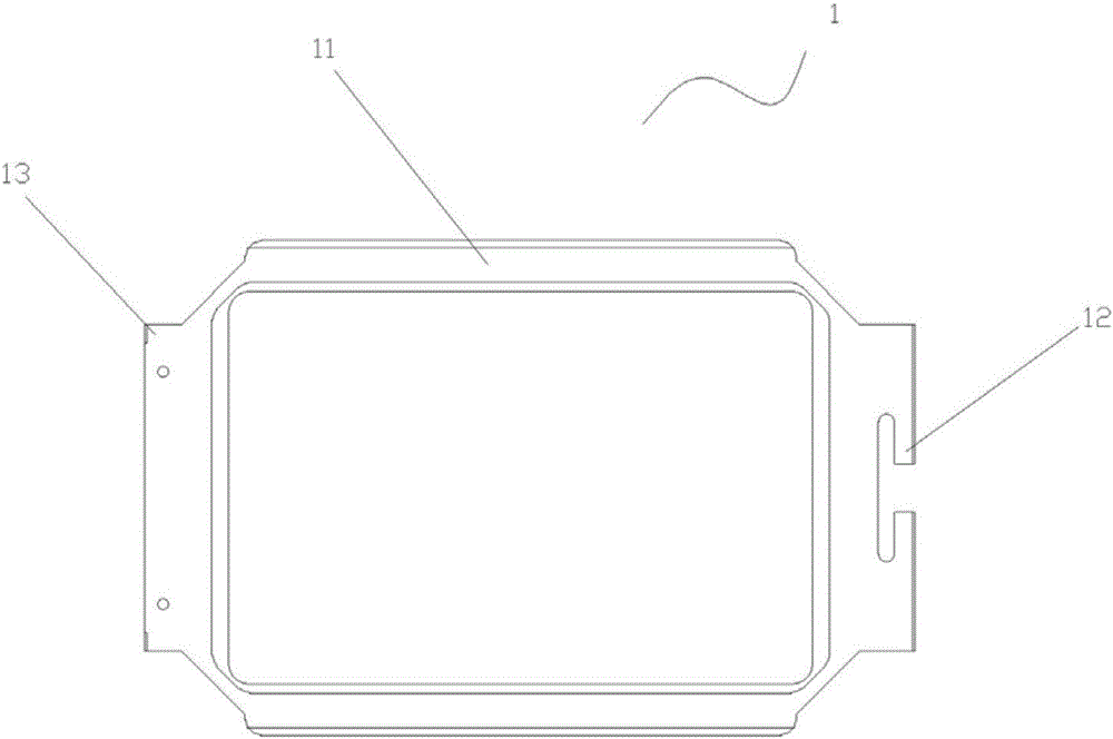
[0020] An automatic capping device, such as figure 1 , 3 As shown, it includes a bracket 1 and a matching portion 2. The bracket 1 includes a bracket body 11, a traction portion 12, and a stop 13; the matching portion 2 includes two oppositely arranged piers, and the inner sides of the two piers are provided with The guide wheel 21 and the inclined rail 22 are provided with a baffle 23 on the front end surface of the pier. Through the cooperation of the bracket 1 and the mating part 2, the combined cover body can realize capping and detaching during the relative movement of the bracket...


PUM


Abstract

The invention relates to the technical field of machinery, and particularly discloses an automatic capping and decapping device. The automatic capping and decapping device is used for capping and decapping of a combined cap. The combined cap comprises an upper cap body and a lower cap body. The capping and decapping device comprises a bracket and a matching part. The bracket comprises a bracket body, a pulling part and a stop block. The matching part comprises two opposite pier blocks. The inner side faces of the two pier blocks are each provided with a guiding wheel and an oblique rail. Baffles are arranged on the front end faces of the pier blocks. Through matching of the bracket and the matching part, capping and decapping of the combined cap can be achieved through relative motion of the bracket and the matching part, and the device can be suitable for various laboratory sterile environments and factory small platforms.

Description

Technical field [0001] The invention relates to the technical field of machinery, in particular to an automatic capping device. Background technique [0002] Many laboratories and factories need to use capping and uncapping technology. In the existing technology, manual capping or robotic capping is generally used. However, in some laboratories, real-time observation is required in a sterile environment. It is necessary to repeatedly add and remove the cover, and in some places, the space is small and the robot hand is not suitable. [0003] In order to solve this problem, an automatic cap attaching and detaching device is designed, which can realize the detachment and attaching of the upper cover through the relative movement of the bracket and the matching part. The automatic cap attaching and detaching device has a compact structure, convenient operation, and can adapt to experiments. Rooms, factories, etc. have small spaces, and require sterile environments and repeated caps. ...

Claims


Application Information

Patent Timeline
IPC IPC(8): B25B27/00
CPCB25B27/00
Inventor 裴端卿张骁宋研董建华秦季生骆健忠卢俊樊科黄海飞麦仕文欧阳瑶张凤香
Owner GUANGZHOU INST OF BIOMEDICINE & HEALTH CHINESE ACAD OF SCI
Learn More