Supercharge Your Innovation With Domain-Expert AI Agents!

Methods and systems to determine rotor imbalance

A technology for rotor unbalance and handling subsystems, which is used in static/dynamic balance testing, blade support elements, machine/structural component testing, etc., and can solve problems such as rotor unbalance

Active Publication Date: 2016-08-03
GE GLOBAL SOURCING LLC
View PDF6 Cites 7 Cited by
  • Summary
  • Abstract
  • Description
  • Claims
  • Application Information

AI Technical Summary

Problems solved by technology

Plus, turbochargers operate under harsh and challenging conditions
Harsh and challenging conditions can cause rotor imbalances

Method used


Image

  • Methods and systems to determine rotor imbalance
  • Methods and systems to determine rotor imbalance
  • Methods and systems to determine rotor imbalance

Examples


Embodiment Construction

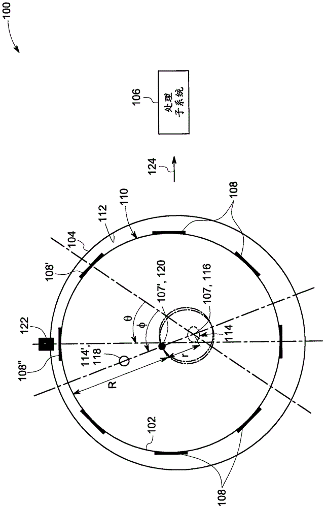
[0031] Rotors in rotating machines may have mass imbalances or load imbalances. For example, a rotor mass imbalance occurs when the center of rotor mass is not on the rotor's axis of rotation. For example, load imbalances may occur due to misfires within the cylinders of an internal combustion engine. The present systems and methods, described in detail below, detect imbalances on the rotor. Additionally, the present systems and methods determine the amount and orientation of the imbalance on the rotor. The present systems and methods determine the presence, amount, and orientation of imbalances based on rotor speed, thus requiring no additional components to be installed. The present systems and methods described herein may be used in a variety of machines, devices, engines, turbines, turbochargers, or the like employing rotors.

[0032] see now figure 1 , shows a block diagram of a system 100 for determining an unbalance on a rotor member 102 (hereinafter "rotor 102") ac...


PUM


Abstract

A system is presented. The system includes a stator component, a rotor component rotating inside the stator component, a plurality of features disposed on the periphery of the stator component or the rotor component, and a processing subsystem for determining at least one of an amount of rotor imbalance and an orientation of the rotor imbalance at least based upon feature-to-feature speed variation of the plurality of features.

Description

Background technique [0001] The engine system generally includes a turbocharger. Turbochargers typically include a compressor rotationally coupled to a turbine via a shaft. Typically when a turbocharger is used with a combustion engine, the turbine of the turbocharger is placed in the path of the exhaust gases leaving the combustion engine. The turbine includes a wheel (hereinafter referred to as "turbine wheel") that is turned by the exhaust flow. The turbine wheel is rotatably coupled to the compressor wheel (hereinafter "compressor wheel"), in a turbocharger. The compressor is positioned in alignment with the air intake system of the combustion engine. The rotation of the turbine caused by the exhaust flow causes the same rotation of the compressor wheel, wherein the rotation of the compressor wheel increases the mass flow of ambient air into the air intake system and also increases the pressure in the air intake system. One or more combustion cylinders in a combustion ...

Claims


Application Information

Patent Timeline
Patent Type & Authority Applications(China)
IPC IPC(8): G01M1/22
CPCG01M1/22F02D23/00F01D5/027G01M1/14
Inventor M·R·帕尼克A·巴塔查亚A·K·安贝卡B·D·沃尔登
Owner GE GLOBAL SOURCING LLC
Features
  • R&D
  • Intellectual Property
  • Life Sciences
  • Materials
  • Tech Scout
  • Unparalleled Data Quality
  • Higher Quality Content
  • 60% Fewer Hallucinations
Learn More