
Backward scattering type infrared silt measurement sensor

A technology for measuring sensors and backscattering, applied in the field of sensors, can solve the problems of not being able to eliminate the influence of sediment particle size factors, affecting the size of scattered light intensity, and being unable to measure the spatial distribution characteristics of scattered light intensity of sediment particles, so as to eliminate The effect of sediment particle size change factors on the influence of sediment measurement results

Inactive Publication Date: 2016-08-03
HEILONGJIANG PROVINCIAL HYDRAULIC RES INST
View PDF10 Cites 7 Cited by
  • Summary
  • Abstract
  • Description
  • Claims
  • Application Information

AI Technical Summary

Problems solved by technology

[0002] At present, the instruments and devices that use the principle of different reflection and scattering intensities of infrared rays in different concentrations of sand-laden water to measure sediment concentration only consider the influence of sediment concentration factors on the intensity of scattered light. Factors such as diameter and color also affect the size of the scattered light intensity
Existing sediment sensors are multiple infrared light sources corresponding to a photodetector, and multiple infrared light sources and photodetectors are fixed at the same angle. Such an optical path structure can only detect the scattered light intensity at a fixed angle in space, and cannot measure The spatial distribution characteristics of the scattered light intensity of sediment particles cannot eliminate the influence of sediment particle size factors on the measurement results
This is the reason why the existing infrared sand measuring instrument can achieve high precision in the measurement results when the average particle size of the sediment does not change much, but when the average particle size of the sediment changes, the measurement results deviate greatly. , it is necessary to re-calibrate the instrument for the changed particle size before it can be used normally, which seriously limits the practicability of the infrared sand measuring instrument

Method used


Image

  • Backward scattering type infrared silt measurement sensor

Examples


Embodiment Construction

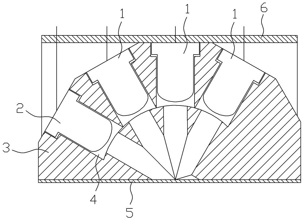
[0007] Such as figure 1 As shown, the backscattering infrared sediment measurement sensor includes a photodetector 1, an infrared light source 2 and an angle positioning block 3 for fixing the photodetector 1 and the infrared light source 2. The direction is provided with at least two described photodetectors 1 that are at different angles with the incident light direction, and is used to receive the infrared light emitted by the sediment solution to be measured at different backscattering angles, according to the scattered light intensity distribution of the sediment solution The average particle size of the sediment solution is calculated in reverse by the feature, and then the mathematical model of the sediment concentration is corrected.

[0008] The angle positioning block 3 is provided with several positioning holes 4 for positioning the angles of the components, and the photodetector 1 and the infrared light source 2 are respectively fixed in the positioning holes 4 . ...


PUM


Abstract

The invention discloses relates to the technical field of sensors, in particular to a backward scattering type infrared silt measurement sensor for measuring the silt content of water flow .The sensor comprises photoelectric detectors (1), an infrared light source (2) and an angle positioning block (3) used for fixing the photoelectric detectors (1) and the infrared light source (2); the two or more photoelectric detectors (1) which are at different angles relative to the incidence light direction are arranged in the direction opposite to an incidence light beam of the infrared light source (2) and used for receiving infrared light emitted by a to-be-measured silt solution at different backward scattering angles; according to the scattered light intensity distribution features of the silt solution, the mean grain size of the silt solution is calculated reversely, and a silt concentration mathematic model is amended .By means of the sensor, spatial distribution of the silt particle scattered light can be detected; influence of the element of grain size variation of silt on the silt measurement result is eliminated, and the infrared silt measurement sensor can have the function of measuring the mean grain size of the silt.

Description

technical field [0001] The invention relates to the technical field of sensors, in particular to a backscattering infrared sediment sensor for measuring the sediment content of water flow. Background technique [0002] At present, the instruments and devices that use the principle of different reflection and scattering intensities of infrared rays in different concentrations of sand-laden water to measure sediment concentration only consider the influence of sediment concentration factors on the intensity of scattered light. Factors such as diameter and color also affect the size of the scattered light intensity. Existing sediment sensors are multiple infrared light sources corresponding to a photodetector, and multiple infrared light sources and photodetectors are fixed at the same angle. Such an optical path structure can only detect the scattered light intensity at a fixed angle in space, and cannot measure The spatial distribution characteristics of the scattered light ...

Claims


Application Information

Patent Timeline
Patent Type & Authority Applications(China)
IPC IPC(8): G01N21/53G01N21/01
CPCG01N21/01G01N21/53G01N2021/4711
Inventor 李勇涛陈英智焦宝明李立新李成杰
Owner HEILONGJIANG PROVINCIAL HYDRAULIC RES INST
Learn More