A half-wave shunt type LED lamp driving device

A technology of LED lights and driving devices, applied in lighting devices, light sources, electrical components, etc., can solve problems such as light flickering, and achieve high application value

Active Publication Date: 2018-02-02
SHENZHEN POWER2CONTROL SMART TECH CO LTD
View PDF7 Cites 0 Cited by
  • Summary
  • Abstract
  • Description
  • Claims
  • Application Information

AI Technical Summary

Problems solved by technology

[0003] However, if the leakage current of the single live wire control panel does not match the minimum "non-lighting" leakage current of the LED fixture (this is a common phenomenon), the light will flicker, which has become the biggest problem facing the industry. Developmental Disabilities

Method used


Image

  • A half-wave shunt type LED lamp driving device
  • A half-wave shunt type LED lamp driving device
  • A half-wave shunt type LED lamp driving device

Examples


Embodiment 1

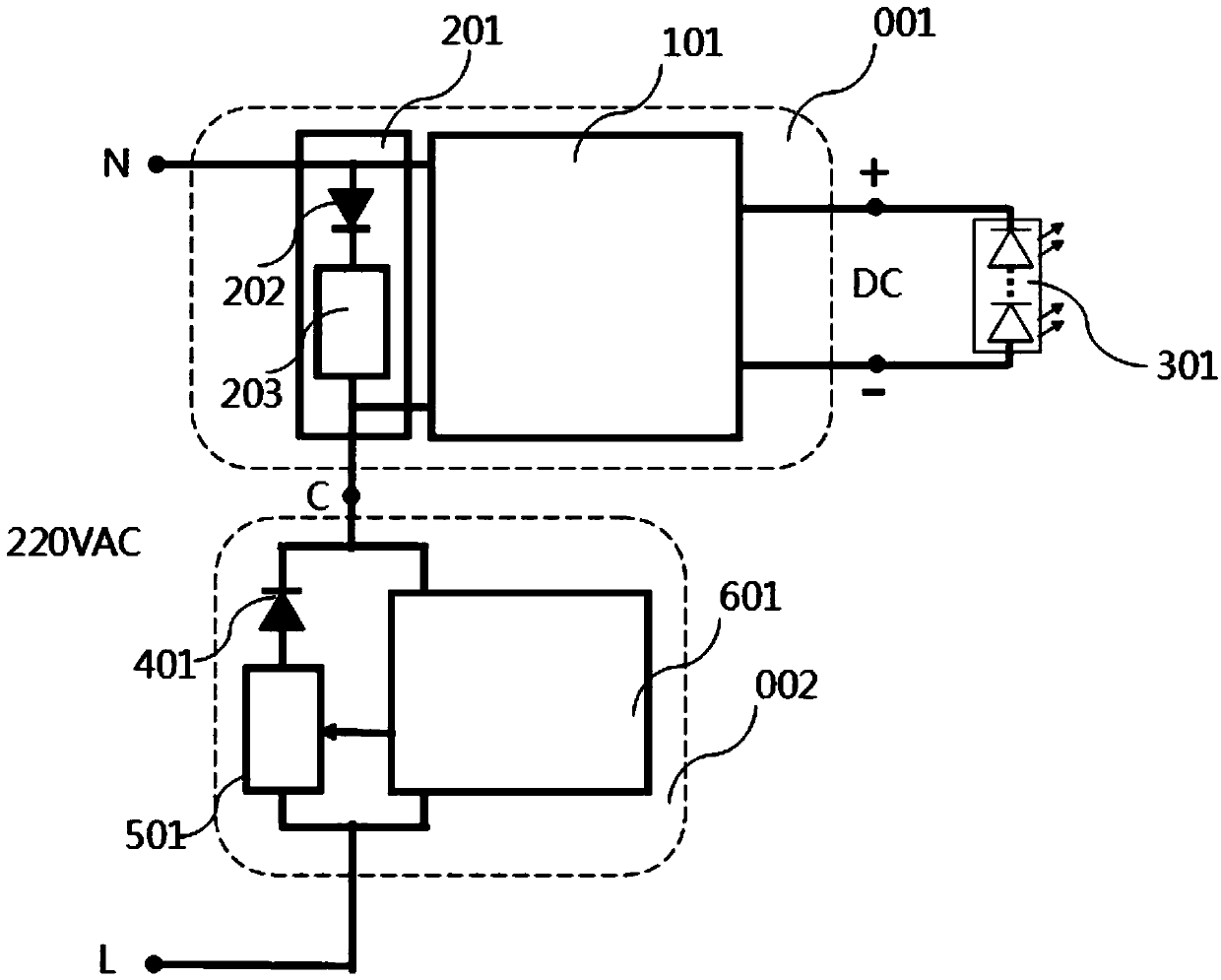
[0023] Embodiment 1: Single FireWire smart device control application for LED lamps.

[0024] see figure 2 , the half-wave shunt LED lamp drive device 001 and the intelligent control device 002 are connected in series in the 220VAC alternating current circuit, the LED lamp circuit shunt diode 401 in the intelligent control device 002 is connected in series with the controllable switch element 501, and then connected to the intelligent control circuit 601 are connected in parallel and then connected in series in the AC circuit. LED lamp loop shunt diode 401 is opposite to the connection direction of AC loop half-wave power supply shunt diode 202 in the loop. The controllable switch element 501 is controlled by the intelligent control circuit 601 to implement switch control of the loop of the LED lamp driving power supply circuit 101.

[0025] When the AC input is a positive half-wave, the AC circuit half-wave power supply shunt diode 202 is turned on to provide half-wave pow...

Embodiment 2

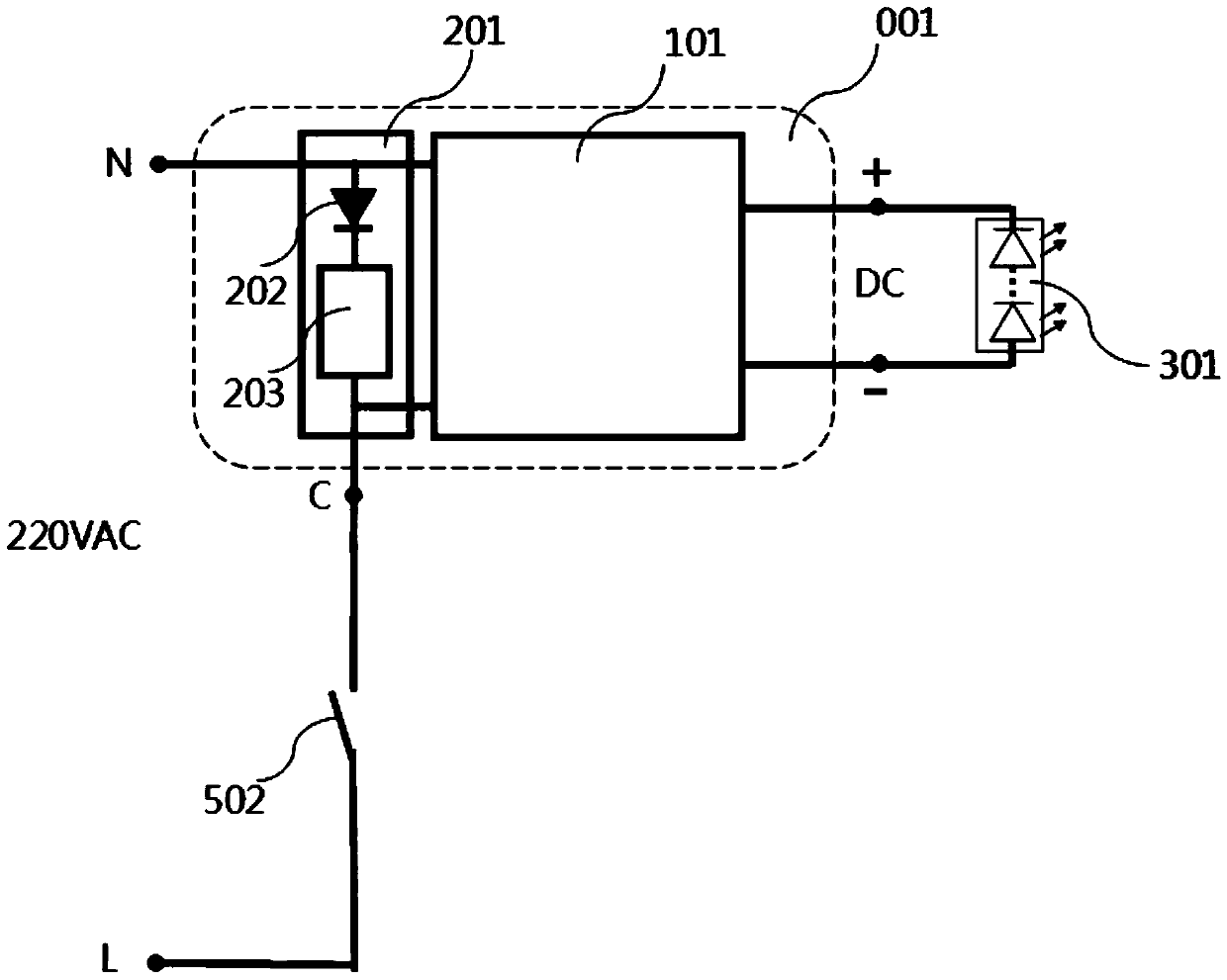
[0027] Embodiment 2: For the application of mechanical switch control of LED lamps.

[0028] see image 3 , the half-wave shunt type LED lamp driving device 001 is connected in series with the mechanical switch 502 in the same loop, when the mechanical switch 502 is in a closed state and the AC input is a positive half-wave, the AC loop half-wave power supply shunt diode 202 is turned on, and at the same time , the recoverable overcurrent protection device or circuit 203 enters an open circuit or high resistance state, which is equivalent to an open circuit; and when the AC input is a negative half-wave, the AC circuit half-wave power supply shunt diode 202 is cut off. At this time, the LED lamp drive power circuit 101 obtains the half-wave power supply, so that the LED lamp 301 is turned on.

[0029] When the mechanical switch 502 is in an open state, the entire circuit is disconnected, and the LED lamp driving power supply circuit 101 cannot obtain power, so that the LED la...


PUM


Abstract

The invention discloses a half-wave shunting type LED lamp driving device, which is composed of an LED lamp driving power circuit and a half-wave shunting circuit connected in parallel to the power input end. The LED lamp driving power circuit has an AC input in the range of 90-250VAC or 50-120VAC, and the half-wave shunt circuit is connected in parallel to the AC input end of the LED lamp driving power circuit. The present invention makes full use of the wide-range input voltage characteristics of the LED lamp drive power circuit and the half-wave shunt circuit connected in parallel at the input end of the drive power circuit to the one-way shunt power supply function of the AC circuit where the LED lamp is located, and conveniently realizes the use of series connection in the same Any control device in the AC circuit of the group realizes the single live wire control of the LED lamp. The invention conveniently realizes the single live wire control of the LED lamp through a simple, reliable and cheap half-wave shunting method, and has extremely high application value in the aspects of smart home and smart lighting control.

Description

technical field [0001] The invention relates to the field of intelligent home lighting control, in particular to a half-wave shunt type LED lamp driving device. Background technique [0002] LED lamps are rapidly spreading to thousands of households. At the same time, intelligent lighting control products such as LEDs are also rapidly spreading to ordinary people's homes. If you want to realize intelligent lighting control without decoration, you must use a single live wire Installation method. At present, the electronic and intelligent control products installed in series with single live wire generally adopt the technology of using the weak leakage current of lamps to provide the working power of single live wire control panel. The "state" is not a true shutdown, but a power-on state in which the human eye cannot see the light when the leakage current is extremely small. [0003] However, if the leakage current of the single live wire control panel does not match the min...

Claims


Application Information

Patent Timeline
Patent Type & Authority Patents(China)
IPC IPC(8): H05B33/08H05B44/00
CPCH05B45/30
Inventor 黎辉赵龙
Owner SHENZHEN POWER2CONTROL SMART TECH CO LTD
Why Eureka
Try Eureka