
Illumination control device and method

A lighting control and lighting device technology, which is applied to lighting devices, electric lamp circuit layout, light sources, etc., can solve the problems of the impact of the life of the lighting device and the huge power consumption of factory lighting.

Active Publication Date: 2015-05-20
SHANDONG JINYU INDUSTRIAL CO LTD
View PDF3 Cites 0 Cited by
  • Summary
  • Abstract
  • Description
  • Claims
  • Application Information

AI Technical Summary

Problems solved by technology

[0003] General factory lighting needs artificial lighting because of the need to carry out operations and production in the workshop. The workshop has very high requirements for lighting. Workers need sufficient lighting when operating machine tools. The lighting can be used to see the road clearly to prevent tripping or bumping. Of course, the power consumption of factory lighting is also huge, so some energy-saving measures are generally adopted. At present, there are illuminance-adjustable light-controlled switches used in factory lighting. It only has an automatic control mode. When the illuminance in the workshop meets the requirements, the switch is automatically turned off. When the illuminance in the workshop cannot meet the requirements, the switch can be adjusted and controlled according to the actual needs of the illuminance. However, when this switch is actually used, If you encounter cloudy conditions, the sun appears and disappears frequently, and the switching action will be performed frequently, and it needs to be turned on manually after it is automatically turned off, which will have a serious impact on the life of the lighting device.

Method used


Image

  • Illumination control device and method
  • Illumination control device and method
  • Illumination control device and method

Examples


Embodiment Construction

[0020] The core of the present invention is to provide a lighting control device to realize multiple control modes of lighting; another core of the present invention is to provide a lighting control method.

[0021] In order to enable those skilled in the art to better understand the solution of the present invention, the present invention will be further described in detail below in conjunction with the accompanying drawings and specific embodiments.

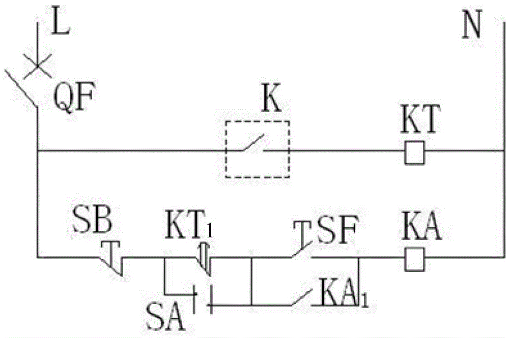
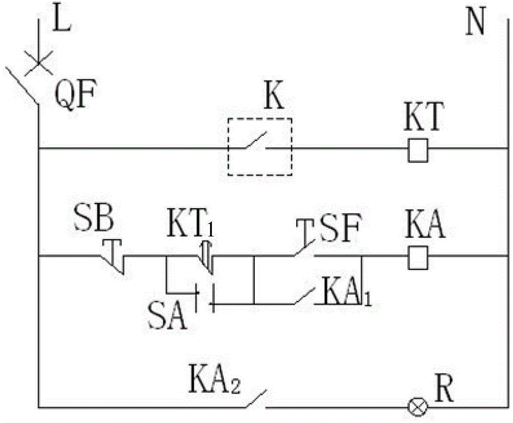
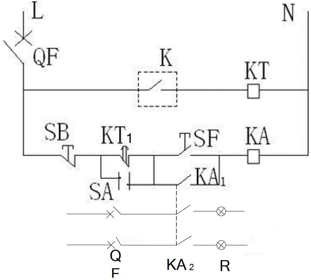
[0022] The lighting control device provided by the embodiment of the present invention includes: a first circuit and a second circuit connected in parallel, wherein the first circuit has a light control switch K and a first relay KT connected in series; The first normally closed switch KT1, the start switch SF and the second relay KA used in conjunction with the first relay KT, the second circuit also has a changeover switch SA connected in parallel with the first normally closed switch KT1 and a second switch SA connected in pa...


PUM


Abstract

The invention discloses an illumination control device, which comprises a first circuit and a second circuit that are connected in parallel, wherein the first circuit is provided with a light-operated switch and a first relay which are connected in series; the second circuit is provided with a first normally-closed switch, a starting switch and a second relay which are connected in sequence and in series and matched with the first relay, and the second circuit is further provided with a conversion switch connected with the normally-closed switch in parallel and a first normally-opened switch matched with the second relay. The illumination control device provided by the invention is provided with the circuit matched with the light-operated switch, and realizes multiple control modes of illumination, comprising an automatic control mode and a manual control mode; the light-operated switch cannot be influenced when being in the automatic control mode; and in cloudy days, the conversion switch is converted into the manual control position to realize that an illumination device is normally brightened, so that frequency starting is not needed and the service life of the illumination device cannot be influenced.

Description

technical field [0001] The invention relates to the technical field of lighting control, in particular to a lighting control device and a control method thereof. Background technique [0002] Lighting is a measure of using various light sources to illuminate working and living places or individual objects. The use of the sun and sky light is called natural lighting; the use of artificial light sources is called artificial lighting. The primary purpose of lighting is to create good visibility and a pleasant environment. [0003] General factory lighting needs artificial lighting because of the need to carry out operations and production in the workshop. The workshop has very high requirements for lighting. Workers need sufficient lighting when operating machine tools. The lighting can be used to see the road clearly to prevent tripping or bumping. Of course, the power consumption of factory lighting is also huge, so some energy-saving measures are generally adopted. At pres...

Claims


Application Information

Patent Timeline
Patent Type & Authority Patents(China)
IPC IPC(8): H05B37/02
Inventor 孙振亮
Owner SHANDONG JINYU INDUSTRIAL CO LTD
Learn More