Supercharge Your Innovation With Domain-Expert AI Agents!

Handheld power tool and operation method thereof

A power tool and hand-held technology, applied in the field of hand-held power tools, can solve the problems of inconvenient operation, unsafe operation, easy to produce fatigue, etc., and achieve the effects of convenient operation, safe operation and labor-saving operation.

Inactive Publication Date: 2016-08-10
POSITEC POWER TOOLS (SUZHOU) CO LTD
View PDF8 Cites 14 Cited by
  • Summary
  • Abstract
  • Description
  • Claims
  • Application Information

AI Technical Summary

Problems solved by technology

In the prior art, a three-jaw chuck is used to clamp the drill bit. The work chuck is made of metal and has a complex structure, so the weight is heavy; while the other work chuck is used to clamp the screwdriver head. Torque adjustment is required when the head performs the work of screwing. Usually, a mechanical control mechanism is provided at the output end of the fuselage close to the output shaft to realize torque adjustment. When these functional parts with complex structure and heavy weight are applied to the gun When the drilling tool is on, the center of gravity of the whole machine is biased to the side of the work chuck, and there is still a horizontal distance between the center of gravity and the grip of the handle, so that the operator's wrist bears torque during the operation, which is prone to fatigue
[0004] In addition, the work chuck needs to release the coupling between the work chuck and the output shaft or the lock between the work chuck and the housing before changing the position. In the prior art, the operator needs to use one hand to release the lock, usually This kind of operating part needs to keep pressing until the work chuck position conversion is completed. For tools that need to manually perform work chuck position conversion, the operator must use the hand that originally held the handle to complete the conversion action. In this way, the operation Operators will frequently change hands to operate, which is extremely inconvenient to operate. For certain workplaces, such as high altitude, such operations are not safe

Method used


Image

  • Handheld power tool and operation method thereof
  • Handheld power tool and operation method thereof
  • Handheld power tool and operation method thereof

Examples


Embodiment Construction

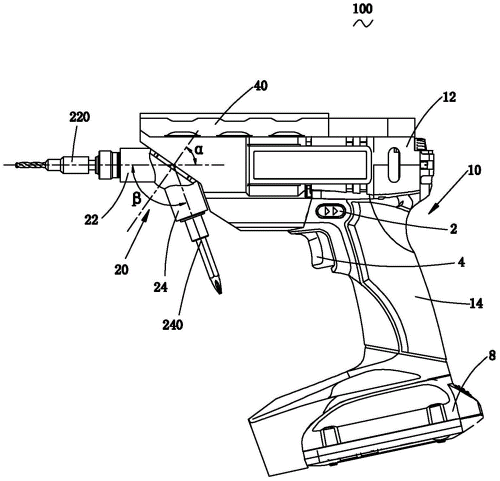
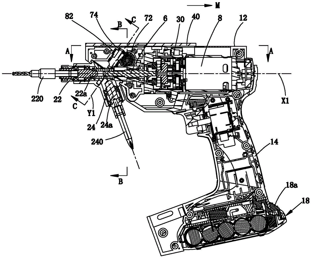
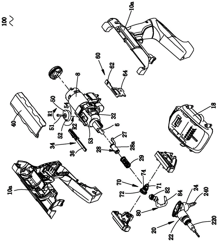
[0166] refer to Figure 1 to Figure 3 As shown, the hand-held power tool 100 of the present invention is provided with a housing 10, wherein the housing 10 is formed by connecting two Huff-type half-shells 10a. The power system includes the motor 8 accommodated in the housing 10 . The motor 8 in this embodiment is an electric motor, and other types of motors, such as an air motor, a fuel motor, etc., can also be used instead. The housing 10 includes a main housing 12 accommodating the motor 8 , and a handle 14 connected to the main housing 12 , the main housing 12 extending in the longitudinal direction, and the handle 14 being arranged at an angle to the main housing 12 . In this embodiment, the main casing 12 and the handle 14 of the multifunctional electric drill 100 are arranged substantially vertically. The end of the handle 14 away from the motor 8 is provided with an energy unit that provides energy for the motor 8. The energy unit in this embodiment uses a battery pac...


PUM

PropertyMeasurementUnit
lengthaaaaaaaaaa
lengthaaaaaaaaaa

Abstract

The invention provides a handheld power tool and an operation method thereof. The handheld power tool comprises a shell body, a handle, a switch, a motor, an output shaft and a working assembly. The working assembly comprises at least two working clamping heads, and each working clamping head comprises a working shaft. The handheld power tool further comprises a control mechanism for conducting position locking on the working assembly relative to the shell body. The control mechanism comprises a control piece which is close to the switch and movably arranged relative to the shell body. The control piece is used for operationally releasing position locking of the working assembly and controlling the output shaft to be disengaged from matched connection with one of the working shafts. Position conversion of the working clamping heads can be completed through one hand with the help of other parts of the body of an operator, and operation is convenient and reliable.

Description

technical field [0001] The present invention relates to a hand-held power tool, in particular to a hand-held power tool with at least two working chucks, and an operating method of the hand-held power tool. Background technique [0002] As a hand-held power tool, such as an electric drill, used for drilling workpieces such as wooden boards, etc., the working head used is a drill bit; such as a screwdriver, which can be used to tighten or loosen screws, and the working head used is a screwdriver head. The spindle of this type of hand-held power tool is usually mounted with a work chuck for holding the type of work head required for the job, and this type of work head can have different specifications. When the working head needs to be replaced for other work, the original working head needs to be disassembled first and replaced with a different working head. The process of this work head replacement operation is very cumbersome. [0003] At present, there are some gundrill...

Claims


Application Information

Patent Timeline
Patent Type & Authority Applications(China)
IPC IPC(8): B25F5/00B23B45/02B25B21/00
CPCB23B45/02B25B21/00B25F5/00B25F3/00B25F5/02
Inventor 钟红风谢明健张士松庞晓丽吴建张锦平
Owner POSITEC POWER TOOLS (SUZHOU) CO LTD
Features
  • R&D
  • Intellectual Property
  • Life Sciences
  • Materials
  • Tech Scout
  • Unparalleled Data Quality
  • Higher Quality Content
  • 60% Fewer Hallucinations
Learn More