Handheld power tool and operation method thereof

The technology of a power tool and operation method, which is applied in the field of hand-held power tools, can solve the problems of inconvenient operation, unsafe operation, heavy weight, etc., and achieve the effect of convenient operation, safe operation and convenient operation

Active Publication Date: 2017-08-08
POSITEC POWER TOOLS (SUZHOU) CO LTD
View PDF6 Cites 2 Cited by
  • Summary
  • Abstract
  • Description
  • Claims
  • Application Information

AI Technical Summary

Problems solved by technology

In the prior art, a three-jaw chuck is used to clamp the drill bit. The work chuck is made of metal and has a complex structure, so the weight is heavy; while the other work chuck is used to clamp the screwdriver head. Torque adjustment is required when the head performs the work of screwing. Usually, a mechanical control mechanism is provided at the output end of the fuselage close to the output shaft to realize torque adjustment. When these functional parts with complex structure and heavy weight are applied to the gun When the drilling tool is on, the center of gravity of the whole machine is biased to the side of the work chuck, and there is still a horizontal distance between the center of gravity and the grip of the handle, so that the operator's wrist bears torque during the operation, which is prone to fatigue
[0004] In addition, the work chuck needs to release the coupling between the work chuck and the output shaft or the lock between the work chuck and the housing before changing the position. In the prior art, the operator needs to use one hand to release the lock, usually This kind of operating part needs to keep pressing until the work chuck position conversion is completed. For tools that need to manually perform work chuck position conversion, the operator must use the hand that originally held the handle to complete the conversion action. In this way, the operation Operators will frequently change hands to operate, which is extremely inconvenient to operate. For certain workplaces, such as high altitude, such operations are not safe

Method used


Image

  • Handheld power tool and operation method thereof
  • Handheld power tool and operation method thereof
  • Handheld power tool and operation method thereof

Examples


Embodiment Construction

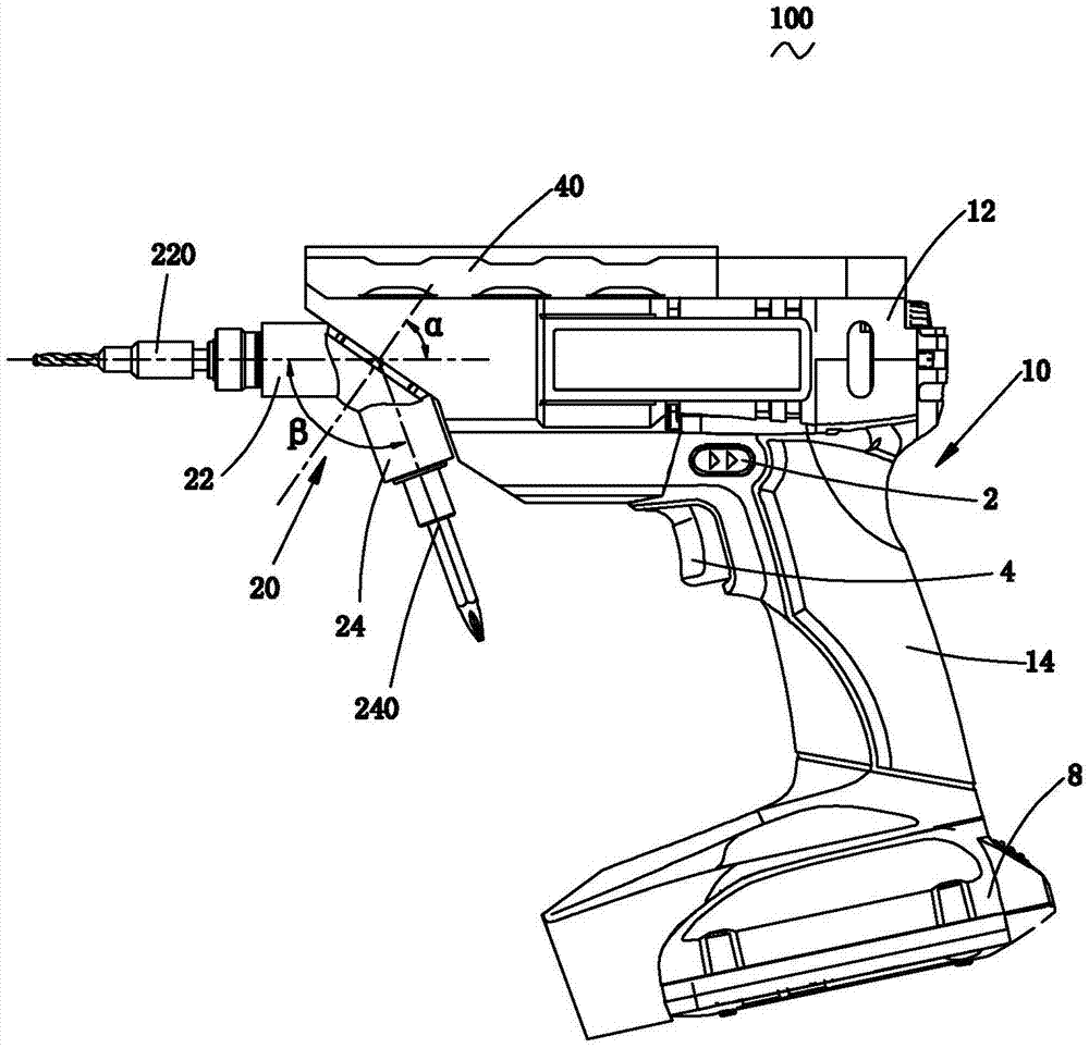
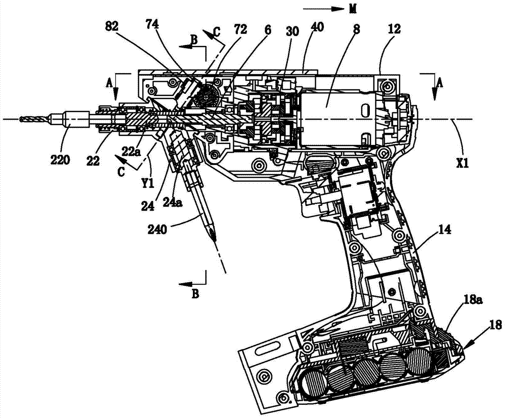
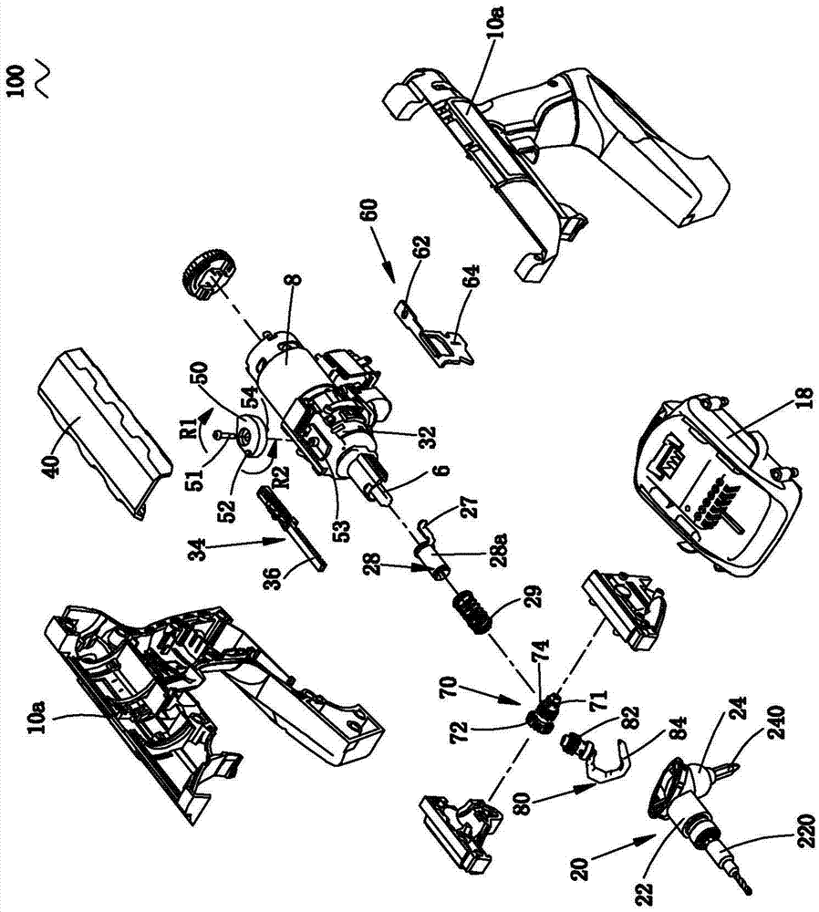
[0166] refer to Figure 1 to Figure 3 As shown, the hand-held power tool 100 of the present invention is provided with a casing 10, wherein the casing 10 is composed of two half-shells 10a of Huff type connected. The power system includes a motor 8 housed in the casing 10. The motor 8 in this embodiment is an electric motor, and other types of motors, such as air motors and fuel motors, can also be used instead. The housing 10 includes a main housing 12 for housing the motor 8 , and a handle 14 connected to the main housing 12 , the main housing 12 extends along the longitudinal direction, and the handle 14 is arranged at an angle to the main housing 12 . In this embodiment, the main housing 12 and the handle 14 of the multifunctional electric drill 100 are arranged approximately vertically. The end of the handle 14 away from the motor 8 is provided with an energy unit that provides energy for the motor 8. The energy unit in this embodiment uses a battery pack 18, which is de...


PUM


Abstract

The invention provides a handheld power tool and an operation method thereof. The handheld power tool comprises a shell, a handle, a switch, a motor, an output shaft and a work assembly. The work assembly comprises at least two work chucks, wherein each of the work chucks includes a work shaft. The handheld power tool further comprises a control mechanism used for locking the position, relative to the shell, of the work assembly. The control mechanism comprises a control part which is adjacent to the switch and moves relative to the shell, and the control part can be used for releasing position locking of the work assembly in an operable manner and controlling one of the output shaft and the work shaft to disengage from matched connection. The position conversion of the work chucks can depend on other parts of the body of an operator, the operation can be completed with the single hand, and the operation is convenient and reliable.

Description

technical field [0001] The present invention relates to a hand-held power tool, in particular to a hand-held power tool with at least two working chucks, and an operating method of the hand-held power tool. Background technique [0002] As a hand-held power tool, such as an electric drill, it is used to drill holes in workpieces such as wood boards, and the working head used is a drill bit; such as a screwdriver, which can be used to tighten or loosen screws, and the working head used is a screwdriver head. The main shaft of such hand-held power tools is usually equipped with a working chuck for clamping a type of working head required for the work, and the working head of this type may have different specifications. When it is necessary to replace the working head for other work, it is necessary to disassemble the original working head and replace it with a different working head. The process of this working head replacement operation is very cumbersome. [0003] At pres...

Claims


Application Information

Patent Timeline
Patent Type & Authority Applications(China)
IPC IPC(8): B25F3/00B25F5/00
CPCB25F3/00B25F5/00
Inventor 钟红风谢明健张士松庞晓丽吴建张锦平
Owner POSITEC POWER TOOLS (SUZHOU) CO LTD
Why Eureka
Try Eureka