Slide rail mechanism and refrigerator with same

A technology of slide rails and cabinets, applied in the field of slide rail mechanisms and refrigerators with it, can solve problems such as easy wear, poor user experience, and noise generation, and achieve the effect of convenient use

Active Publication Date: 2018-04-20
HAIER SMART HOME CO LTD
View PDF7 Cites 0 Cited by
  • Summary
  • Abstract
  • Description
  • Claims
  • Application Information

AI Technical Summary

Problems solved by technology

[0002] At present, the three-section slide rails on the market mainly have the following problems in practical application: First, noise is generated during use: the existing three-section slide rails use the upper rail to run first, and when the upper rail travel distance reaches the extreme, use the upper rail Contact and collide with the limit device of the middle rail, and pull out the middle rail; also use the limit device of the middle rail and the lower rail to contact and collide, to reach the distance that the middle rail is pulled to reach the pole; and the limit device is between the upper rail and the middle rail , The noise of "peddling, pedaling" is generated during the contact and collision between the middle rail and the lower rail, which brings high-frequency noise to the user
In practical application, with the increase in the number of times the three-section slide rail is used, the internal steel balls and the upper rail, lower rail, and middle rail are prone to wear, resulting in a gradual decrease in the gap distance between the upper rail and the lower rail. The distance between the rail and the base connection is extremely small. At this time, the reduction of the gap distance is likely to cause interference between the upper rail and / or the lower rail and the base connection, or even jamming
Therefore, there is a problem in the reliability of the three-section slide rail in the prior art
[0004] In addition, manually opening and closing the drawer will make the user experience not good, and the user's manual opening and closing is easy to damage the synchronization mechanism

Method used


Image

  • Slide rail mechanism and refrigerator with same
  • Slide rail mechanism and refrigerator with same
  • Slide rail mechanism and refrigerator with same

Examples


Embodiment Construction

[0028] The present invention will be described in detail below in conjunction with specific embodiments shown in the accompanying drawings. However, these embodiments do not limit the present invention, and any structural, method, or functional changes made by those skilled in the art according to these embodiments are included in the protection scope of the present invention.

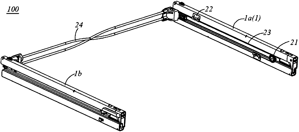
[0029] Such as figure 1 As shown, the present invention provides a slide rail mechanism 100 for pulling out or pushing a drawer (not shown) in a box, including two sets of slide rail assemblies 1 oppositely arranged. Of course, the slide rail mechanism 100 can also be used for drawing, expanding or contracting other structures. It should be noted that two sets of slide rail assemblies 1 can be arranged left and right. In other embodiments, two sets of slide rail assemblies 1 can also be arranged up and down. In the present invention, two sets of slide rail assemblies 1 are arranged left and right as a...


PUM


Abstract

The invention discloses a sliding rail mechanism and a refrigerator with the sliding rail mechanism. The sliding rail mechanism comprises two groups of sliding rail assemblies, a synchronous mechanism and a motor assembly, wherein each sliding rail assembly is provided with an upper rail, a middle rail and a lower rail; each middle rail comprises a first connection part, a second connection part and a limiting part; each limiting part comprises a first abutting surface for limiting each upper rail from moving towards each lower rail and a second abutting surface for limiting each lower rail from moving towards each upper rail; the synchronous mechanism comprises steering pieces, fixing pieces and tensioning pieces; the tensioning pieces are arranged between the fixing pieces of the two sliding rail assemblies in a surrounding manner; the motor assembly is provided with a first connection end and a second connection end for winding or unwinding the tensioning pieces; the tensioning pieces are respectively connected to the first connection end and the second connection end in a winding manner; the motor assembly drives the tensioning pieces to be shrunk through one of the first connection end and the second connection end, and drives the tensioning pieces to be released through the other one of the first connection end and the second connection end, so that the tensioning pieces can move. The limiting parts control distances between the upper rails and the lower rails under the limiting action, and drawers can be pulled and pushed automatically.

Description

technical field [0001] The invention relates to the field of household appliances, in particular to a slide rail mechanism and a refrigerator having the same. Background technique [0002] At present, the three-section slide rails on the market mainly have the following problems in practical application: First, noise is generated during use: the existing three-section slide rails use the upper rail to run first, and when the upper rail travel distance reaches the extreme, use the upper rail Contact and collide with the limit device of the middle rail, and pull out the middle rail; also use the limit device of the middle rail and the lower rail to contact and collide, to reach the distance that the middle rail is pulled to reach the pole; and the limit device is between the upper rail and the middle rail , The noise of "peddling, pedaling" is generated during the contact and collision between the middle rail and the lower rail, which brings high-frequency noise to the user. ...

Claims


Application Information

Patent Timeline
Patent Type & Authority Patents(China)
IPC IPC(8): F25D25/02
CPCF25D25/025
Inventor 陆日勇费斌刘金林李登强
Owner HAIER SMART HOME CO LTD
Why Eureka
Try Eureka