Eureka AIR delivers breakthrough ideas for toughest innovation challenges, trusted by R&D personnel around the world.

A kind of mask meltblown cloth processing and testing integrated equipment

A melt-blown cloth and integrated technology, which is applied in the field of mask melt-blown cloth processing and detection integrated equipment, can solve the problem of uneven thickness of melt-blown cloth with low melting point fiber melting fiber shrinkage rate, and it is difficult to meet the large-scale production of melt-blown cloth, melt-blown Cloth is stretched and other problems, to achieve the effect of high degree of automation, firm clamping, and improved safety

Active Publication Date: 2021-04-06
常州美康源医疗科技有限公司
View PDF10 Cites 0 Cited by
  • Summary
  • Abstract
  • Description
  • Claims
  • Application Information

AI Technical Summary

Problems solved by technology

[0002] At present, under normal production conditions of melt-blown cloth, there will be uneven thickness of melt-blown cloth due to uneven blending of low-melting point fibers and conventional fibers, incomplete melting of low-melting point fibers, and high shrinkage of fibers, and the melt-blown cloth is relatively thin. It is easy to cause the phenomenon of being stretched, and the short code problem occurs due to the release of tension after the roll is rolled. Therefore, after the melt-blown cloth is produced and formed, it needs to be tested for its tensile strength. In the prior art, people usually pull it manually, and then observe The melt-blown cloth is restored to its state, so as to judge whether it is qualified, but the manual pulling method has a low degree of automation and low detection efficiency, and it is difficult to satisfy the large-scale production of melt-blown cloth

Method used


Image

  • A kind of mask meltblown cloth processing and testing integrated equipment
  • A kind of mask meltblown cloth processing and testing integrated equipment
  • A kind of mask meltblown cloth processing and testing integrated equipment

Examples


Embodiment Construction

[0031] The following will clearly and completely describe the technical solutions in the embodiments of the present invention with reference to the accompanying drawings in the embodiments of the present invention. Obviously, the described embodiments are only some, not all, embodiments of the present invention. Based on the embodiments of the present invention, all other embodiments obtained by persons of ordinary skill in the art without creative efforts fall within the protection scope of the present invention.

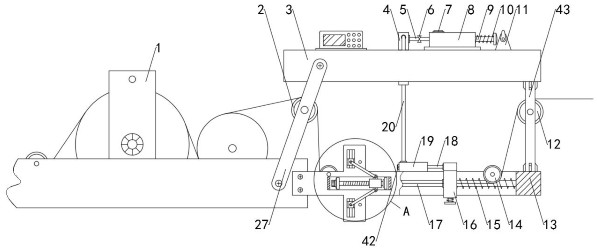
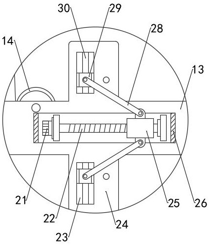
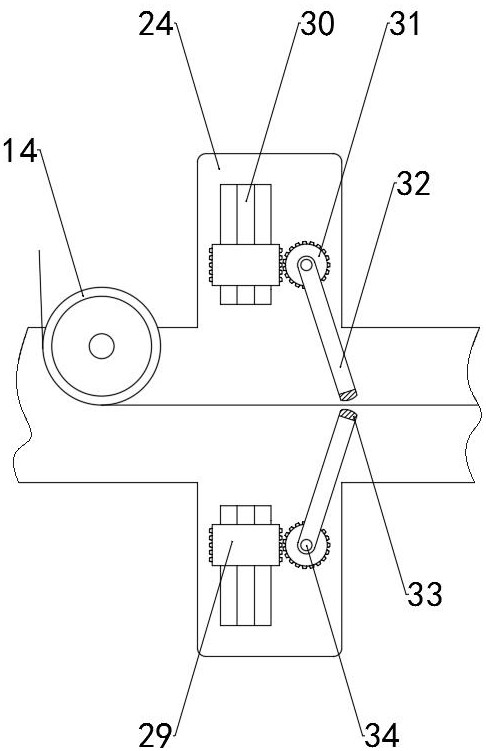
[0032] see Figure 1-6 , the present invention provides a technical solution: an integrated equipment for processing and detecting mask melt-blown cloth, including a processing mechanism 1, a frame 13 is fixed at the end of the processing mechanism 1 and a top plate 3 is fixed on the top of the frame 13 through a column 43, inside the frame 13 Two rollers 14 are installed in the cavity, and the rollers 14 and the frame 13 are rotatably connected by bearings. The ve...


PUM


Abstract

The invention discloses an integrated equipment for processing and detecting mask melt-blown cloth, which includes a processing mechanism. In the present invention, after the production of the melt-blown cloth is completed, the melt-blown cloth passes through the first roller, the second roller, the cavity and the third roller, and through the setting of the motor, the lead screw and the nut pair, the moving block moves in the vertical direction. Under the action of the gear, the rotating rod can drive the clamping arm to fix the melt-blown cloth. Under the repulsion of the electromagnet and the magnet, the splint clamps and fixes the melt-blown cloth. Under the action, piston rod one reciprocates in the horizontal direction, and under the action of check valve one, check valve two, main pipe and branch pipe, it can pressurize the inside of piston barrel two, and piston rod two can push the sliding sleeve to one side Promoted, the automatic pulling of the melt-blown cloth is realized, thereby achieving the effect of automatic machine inspection. Compared with traditional manual inspection, the degree of automation is higher and the detection efficiency is higher, which effectively avoids the problems caused by manual missed inspection and false inspection. loss.

Description

technical field [0001] The invention relates to the technical field of quality inspection of melt-blown cloth production, in particular to an integrated equipment for processing and detecting melt-blown cloth for masks. Background technique [0002] At present, under normal production conditions of melt blown cloth, there will be uneven thickness of melt blown cloth due to uneven blending of low melting point fiber and conventional fiber, incomplete melting of low melting point fiber and high shrinkage rate of fiber, and thinner melt blown cloth It is easy to cause the phenomenon of being stretched, and the short code problem occurs due to the release of tension after rolling. Therefore, after the melt-blown cloth is produced and formed, it needs to be tested for tensile strength. In the prior art, people usually pull it manually, and then observe The melt-blown cloth is restored to the state, so as to judge whether it is qualified, but the manual pulling method has a low de...

Claims


Application Information

Patent Timeline
Patent Type & Authority Patents(China)
IPC IPC(8): G01N3/10G01N3/02G01N3/04
CPCG01N3/02G01N3/04G01N3/10G01N2203/0003G01N2203/0017G01N2203/0044G01N2203/0258G01N2203/0282G01N2203/0452
Inventor 黄培荣
Owner 常州美康源医疗科技有限公司
Why Eureka
Eureka Blog
Learn More