Check patentability & draft patents in minutes with Patsnap Eureka AI!

Decoding performance analysis method and apparatus for decoder

An analysis method and technology of an analysis device, applied in the field of decoding, can solve the problems of the decoder not decoding, the decoding performance of the decoder being reduced, and the crash state, etc.

Active Publication Date: 2016-08-24
BEIJING JIAODA SIGNAL TECH
View PDF4 Cites 0 Cited by
  • Summary
  • Abstract
  • Description
  • Claims
  • Application Information

AI Technical Summary

Problems solved by technology

[0003] Specifically, the decoding performance of the decoder can be considered from two aspects: 1) Decoding time refers to the time from when the decoder receives the correct source code of a frame of message to finally decoding the legal user message, and the decoding time is shorter The shorter the decoding performance, the better; 2) The shortest source code length that can be decoded, when the source codes are all good codes, that is, the source code is not disturbed, the shortest source code length that can be decoded for long messages is 1100 bits, and the shortest message length is 1100 bits. The shortest decodable source code length is 462 bits. However, when the source code is disturbed, the shortest decodable source code length of the long message is greater than 1100 bits, and the shortest decodable source code length of the short message is greater than 462 bits. bit, if the length of the shortest source code that can be decoded is too large, it will cause the decoder not to decode and a crash state will occur
[0004] In the existing technology, large-scale simulation equipment is used to test the function of the BTM machine, or to test the decoding performance of the decoder only when the source code is not disturbed. However, in the field test environment, the source code will be subject to various disturbances , leading to a decrease in the decoding performance of the decoder, and there is no method for analyzing the decoding performance of the decoder when the source code is disturbed in the prior art

Method used


Image

  • Decoding performance analysis method and apparatus for decoder
  • Decoding performance analysis method and apparatus for decoder
  • Decoding performance analysis method and apparatus for decoder

Examples


Embodiment Construction

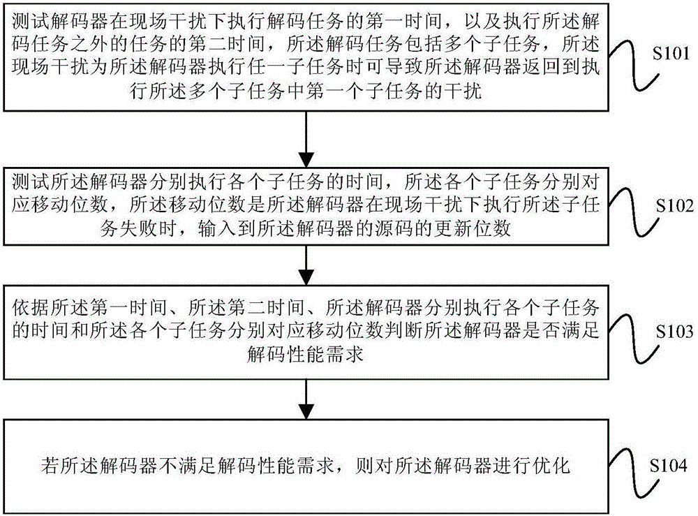
[0020] figure 1 A flow chart of a decoder decoding performance analysis method provided by an embodiment of the present invention; figure 2 The flow chart of the decoding task provided by the embodiment of the present invention. The embodiment of the present invention aims at the lack of a method for analyzing the decoding performance of the decoder when the source code is disturbed in the prior art, and provides a method for analyzing the decoding performance of the decoder. The specific steps of the method are as follows:

[0021] Step S101, test the first time when the decoder performs a decoding task under on-site interference, and the second time when performing tasks other than the decoding task, the decoding task includes a plurality of subtasks, and the on-site interference is the decoding task an interference that may cause the decoder to return to performing a first subtask of the plurality of subtasks while the decoder is performing any subtask;

[0022] Such as ...


PUM


Abstract

The embodiment of the invention provides a decoding performance analysis method and apparatus for a decoder. The method comprises: first time of executing a decoding task by a decoder under field interference as well as second time of executing a task except the decoding task is tested, wherein the decoding task includes a plurality of sub tasks and the field interference refers to the interference causing that the decoder returns to execute a first sub task among the multiple sub tasks when executing any sub task; time of executing all sub tasks by the decoder respectively is tested, wherein all sub tasks correspond to moving digits respectively; according to the first time, the second time, the time executing all sub tasks by the decoder, and the moving digits corresponding to all sub tasks, whether the decoder meets a decoding performance requirement is determined; and if not, the decoder is optimized. Therefore, under the circumstance that the source code is under interference, the decoding performance of the decoder can be analyzed.

Description

technical field [0001] The embodiments of the present invention relate to the technical field of decoding, and in particular to a method and device for analyzing decoding performance of a decoder. Background technique [0002] Transponder systems are now widely used in railway systems, including ground equipment and on-board equipment. BTM is the core equipment in on-board equipment. The core function of BTM is decoding. Specifically, the decoder of BTM is responsible for the TA signal received by BTM to decode. After research, it is found that the decoding performance of the decoder is directly related to the immunity of BTM and the maximum speed of the train using BTM. [0003] Specifically, the decoding performance of the decoder can be considered from two aspects: 1) Decoding time refers to the time from when the decoder receives the correct source code of a frame of message to finally decoding the legal user message, and the decoding time is shorter The shorter the de...

Claims


Application Information

Patent Timeline
IPC IPC(8): H03M13/01H03M13/09
CPCH03M13/015H03M13/091
Inventor 杨婷王耀辉冉娜娜
Owner BEIJING JIAODA SIGNAL TECH
Features
  • R&D
  • Intellectual Property
  • Life Sciences
  • Materials
  • Tech Scout
  • Unparalleled Data Quality
  • Higher Quality Content
  • 60% Fewer Hallucinations
Learn More