
A hydraulic support with pose detection and control functions and its working method

A technology of hydraulic support and control function, applied in mine roof support, support/support, surveying and navigation, etc., can solve the problems of poor adjustment accuracy, continuous oscillation of support posture, poor detection accuracy, etc.

Active Publication Date: 2018-03-23
SHANDONG UNIV OF SCI & TECH
View PDF3 Cites 1 Cited by
  • Summary
  • Abstract
  • Description
  • Claims
  • Application Information

AI Technical Summary

Problems solved by technology

[0006] The Chinese patent document CN103899344B discloses a method for self-adaptive leveling of the top beam of the hydraulic support. The method uses sensors to detect the inclination of the top beam and adjusts the state of the top beam of the support by means of blind motion testing. The patent starts from the stage of initial support of the support. The control has certain limitations, and the blind trial method adopted in this scheme not only consumes a lot of time in the trial and comparison process, but also easily causes the bracket to continue to oscillate due to improper step distance during the adjustment process, which reduces the support of the bracket. The stability of the maintenance work, the adjustment accuracy is poor
[0007] Although some of the current hydraulic supports have pose detection functions, these detection functions only solve how to obtain the pose data of hydraulic supports, and there are many detection data, which are greatly affected by environmental factors and poor detection accuracy; in terms of control functions , the existing support posture control function often adopts the blind motion trial method to control the posture and posture of the support. Therefore, it is necessary to design a new type of hydraulic support with intelligent detection and control functions for the position and posture of the hydraulic support.

Method used


Image

  • A hydraulic support with pose detection and control functions and its working method
  • A hydraulic support with pose detection and control functions and its working method
  • A hydraulic support with pose detection and control functions and its working method

Examples


Embodiment 1

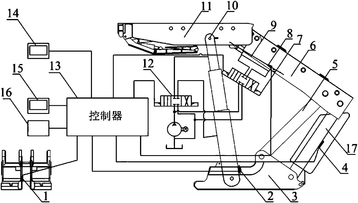
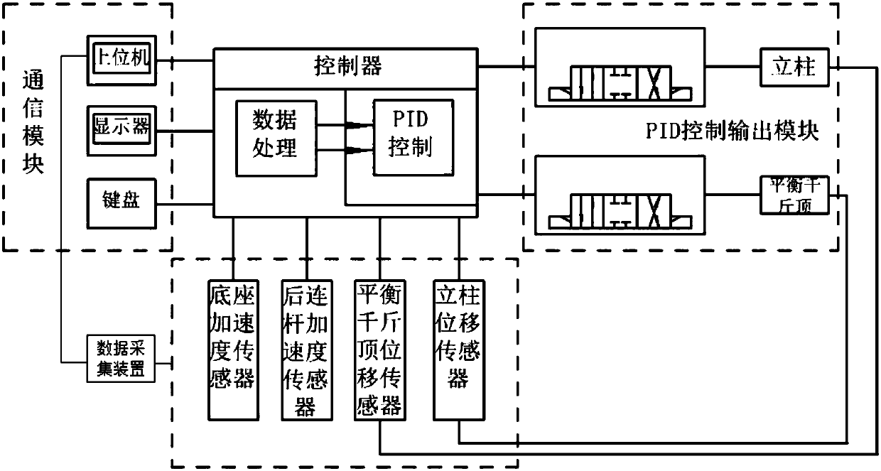
[0094] Such as figure 1 , figure 2As shown, a hydraulic support with pose detection and control functions, the hydraulic support includes a base 3, a column 10, a rear link 17, a shield beam 6, a balance jack 9 and a top beam 11, and a controller 13, Data collection device, the first acceleration sensor 1, the second acceleration sensor 4, the stroke sensor 8, the laser rangefinder 2, the first electromagnetic proportional valve 7 and the second electromagnetic proportional valve 12; the first acceleration sensor 1 is installed on the base 3, the second acceleration sensor 4 is installed on the rear connecting rod 17, the stroke sensor 8 is installed inside the balance jack 9, the laser range finder 2 is installed on the column 10, and the first electromagnetic proportional valve 7 is installed on the hydraulic control circuit of the balance jack Above, the second electromagnetic proportional valve 12 is installed on the column hydraulic control circuit, the first accelerati...

Embodiment 2

[0099] A hydraulic support with pose detection and control functions, the components and their connections are as described in Embodiment 1, the difference is that: the input device uses a touch screen display / input module, the touch screen display / input module and the controller Connection, the touch screen can omit the keyboard, and at the same time, the operation is more convenient and intuitive.

[0100] The controller can also be connected with an external host computer. The host computer needs to be connected with the first acceleration sensor, the second acceleration sensor, the stroke sensor and the laser rangefinder through an external data acquisition device for data acquisition. The upper computer is a PC. Data acquisition The device is the Advantech PCI-1711U data acquisition card, the upper computer is connected with the Advantech PCI-1711U data acquisition card, the Advantech PCI-1711U data acquisition card is connected with the first acceleration sensor, the seco...

Embodiment 3

[0102] Such as Figure 3 to Figure 6 As shown, this embodiment provides a working method of the hydraulic support with pose detection and control functions as described in Embodiment 1, including the following steps,

[0103] (1) Signal collection: the base acceleration measured by the first acceleration sensor, the rear link acceleration measured by the second acceleration sensor, the length of the hydraulic support balance jack measured by the stroke sensor, and the length of the column measured by the laser rangefinder are transmitted To the data acquisition device, the data acquisition device filters the received signal to obtain the original data of acceleration and length, and transmits the original data of acceleration and length to the MSP430F5438a microcontroller;

[0104] The filtering process refers to that the data acquisition device continuously samples N data, and then sorts the collected N data with the principle of heap sequence method, finds the maximum and mi...


PUM


Abstract

The invention relates to a hydraulic bracket with a pose detection and control function and a working method of the hydraulic bracket with the pose detection and control function. The hydraulic support comprises a controller, a data acquisition device, a first acceleration sensor, a second acceleration sensor, a travel sensor, a laser range finder, a first electromagnetic proportional valve and a second electromagnetic proportional valve; data measured by the acceleration sensors, the travel sensor and the laser range finder are transmitted to the controller, real-time all-attitude control is carried out on the pose of the hydraulic support by using PID control rules, and the on-off and the flow rates of the electromagnetic proportional valves are controlled through the controller to regulate fast horizontal ascending and descending of the bracket in a lifting process of the hydraulic support and to realize intelligent adhesion of the hydraulic support when a roof of a working face is inclined so as to improve the support lifting and moving speed and the machine following speed of the hydraulic bracket; the hydraulic support further comprises a pose detection and control system, thereby having more functions, better performances and incomparable advantages.

Description

technical field [0001] The invention relates to a hydraulic support with pose detection and control functions and a working method thereof, belonging to the technical field of hydraulic supports. Background technique [0002] In the fully mechanized mining face, in order to prevent the coal seam roof from falling and ensure the safety of the staff and the normal production, the roof must be supported. The hydraulic support is the necessary supporting equipment for the fully mechanized mining face. Many coal mines in my country have established fully-mechanized mining automation production areas, and equipped with fully-mechanized mining equipment remote monitoring function. The real-time, reliable and intuitive remote monitoring of the hydraulic support can not only grasp the accurate operation status of the hydraulic support in time, but also predict the support quality of the hydraulic support, and adjust the operating parameters of the support according to the inspection ...

Claims


Application Information

Patent Timeline
Patent Type & Authority Patents(China)
IPC IPC(8): E21D23/12E21D23/16E21D15/44G01C1/00
CPCE21D15/44E21D23/12E21D23/16G01C1/00
Inventor 曾庆良孟昭胜万丽荣孔帅王成龙杨扬逯振国刘鹏姜考
Owner SHANDONG UNIV OF SCI & TECH
Learn More