Arbitrary convex polygon block discrete unit method based on distance potential function

A technique of discrete element method and convex polygon, applied in electrical digital data processing, special data processing applications, instruments, etc., can solve problems such as ambiguity in physical meaning

Active Publication Date: 2016-08-31
HOHAI UNIV
View PDF3 Cites 18 Cited by
  • Summary
  • Abstract
  • Description
  • Claims
  • Application Information

AI Technical Summary

Problems solved by technology

[0006] The purpose of the present invention is to overcome the deficiencies in the prior art, providing a discrete element method based on the distance potential function arbitrary convex polygon block, which solves the technical problem of unclear physical meaning in the potential function calculation method in the prior art

Method used

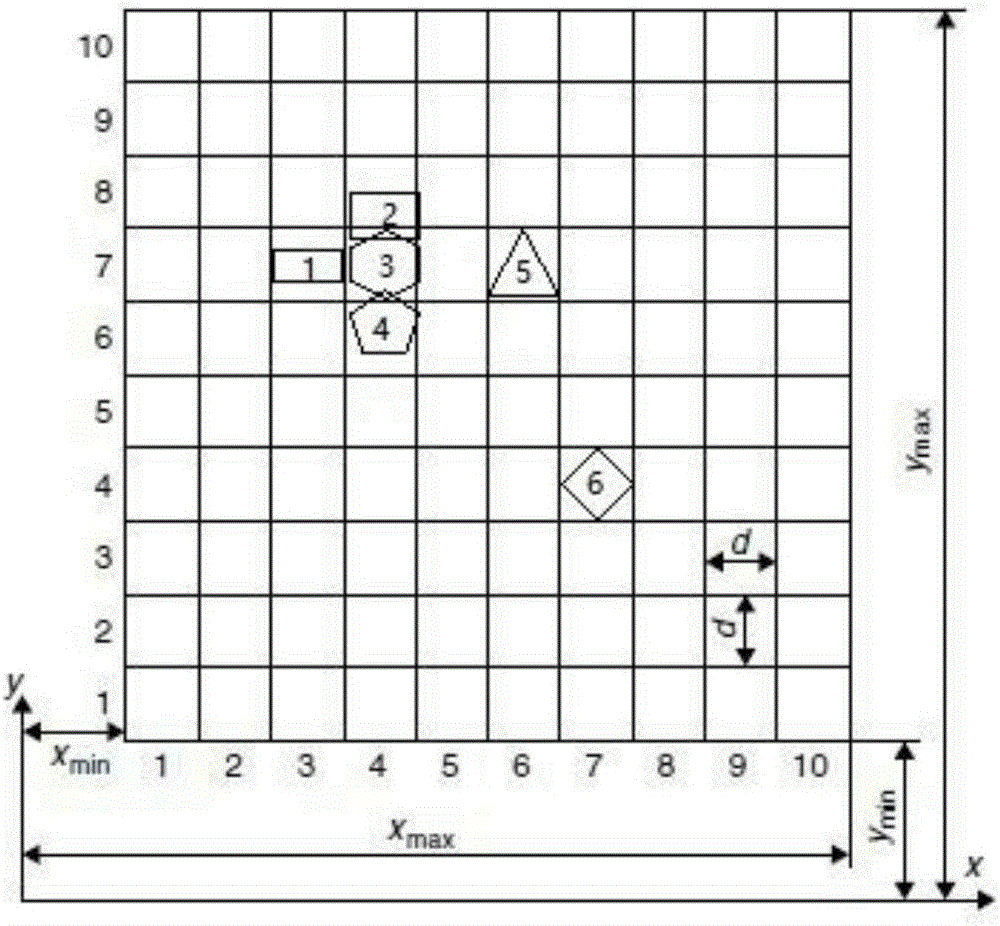
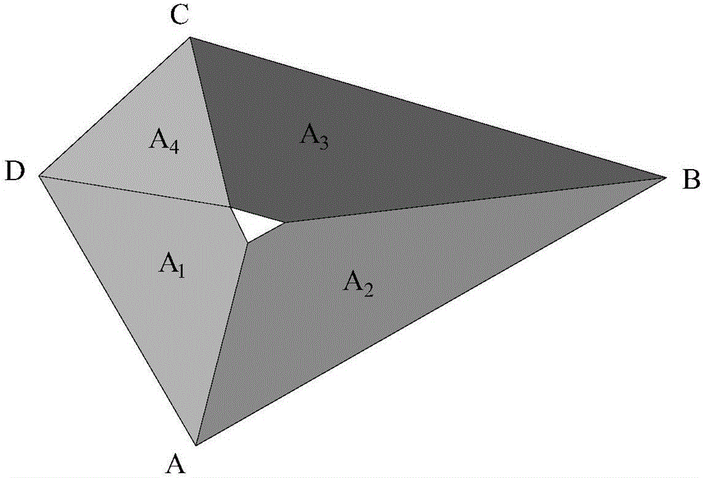
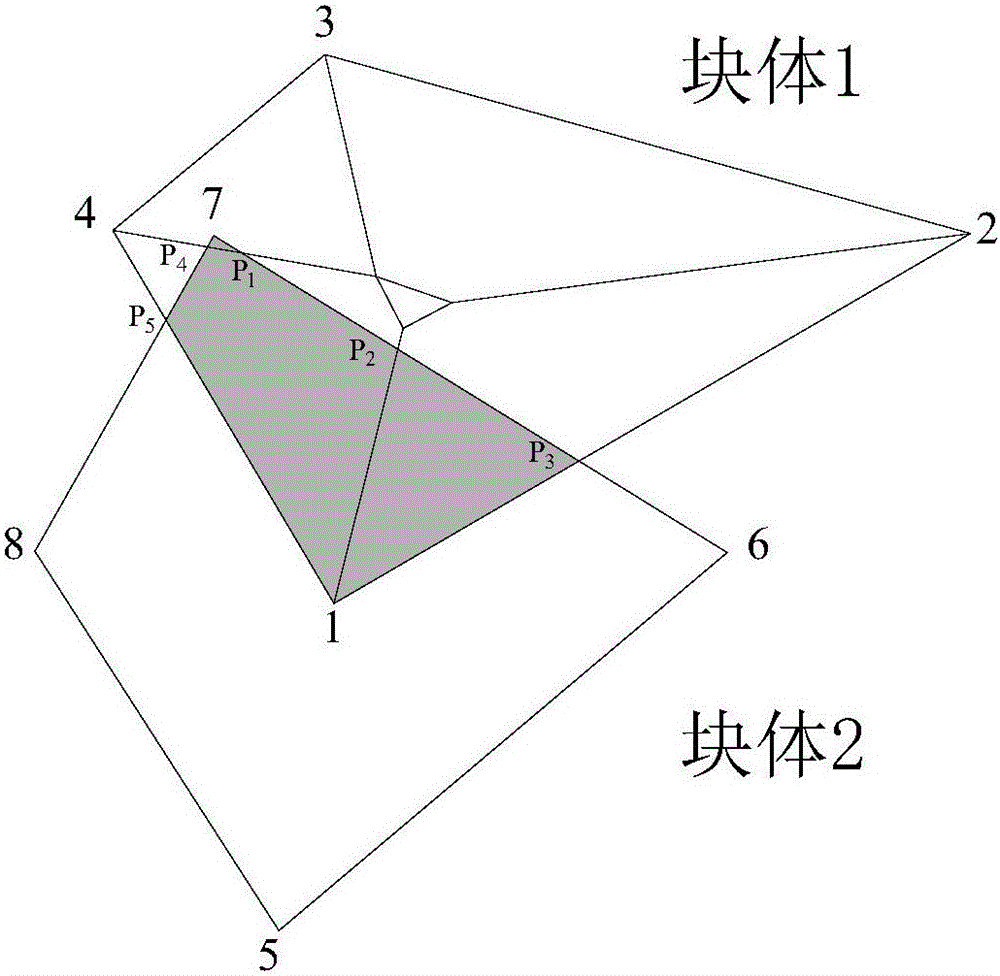

Image

  • Arbitrary convex polygon block discrete unit method based on distance potential function
  • Arbitrary convex polygon block discrete unit method based on distance potential function
  • Arbitrary convex polygon block discrete unit method based on distance potential function

Examples


Embodiment 1

[0167] The movement form of the ore falling into the trough frame at a certain speed, the trough frame is a rectangular frame, that is, the movement form of the polygonal ore block unit within a certain shape boundary, such as Figure 5As shown, four ore blocks move downward at a speed of 0.08m / s. Using the method provided by the present invention, a discrete element model is established for the ore-boundary. Now the four ore blocks are divided into 35 block discrete units , that is to calculate and analyze the movement of 35 block units.

[0168] Figures 6 to 10 It is the movement process diagram of the ore block after the ore block starts to contact the tank frame. In the discrete element model, all block units move downward at a speed of 0.08m / s. When the lowermost block unit contacts the boundary, the distance between the block unit and the block unit and between the block unit and the boundary Due to the contact force and moment generated by the contact, the resultant ...

Embodiment 2

[0172] The funnel of a mining site is filled with collapsed and irregular ores of different sizes. Open the gate of the funnel, and under the action of self-weight, the movement form of the ore after it is released from the funnel, that is, the polygonal ore block unit is within a certain shape boundary The motion form of the ore, using the method provided by the present invention, establishes a discrete element model for the ore-boundary, such as Figure 12 As shown, a total of 309 ore body discrete units are divided, 162 funnel and trough frame discrete units are divided, and the funnel and trough frame are fixed.

[0173] Figure 12 is the initial state of the ore in the hopper, Figure 13 to Figure 19 After the gate of the funnel mouth is opened, it is the geometric shape when drawing ore. The ore bodies are affected by gravity and contact each other, resulting in contact force and moment, the speed and acceleration of the ore body change accordingly, and the ore body mo...


PUM


Abstract

The present invention discloses an arbitrary convex polygon block discrete unit method based on a distance potential function. The method mainly comprises the following steps of establishing an ore-boundary discrete model; performing contact detection on all block units by using an NBS contact detection method, and obtaining each block unit and the block units in contact with each block unit; performing contact force calculation on the block units in contact with each other through a block discrete unit distance potential function, and obtaining contact force and moment acting on the block units; and furthermore calculating speed and displacement of the block units by a velocity verlet algorithm, and finally gradually updating displacement of the ore block units, namely the specific motion morphology thereof. The definition of the distance potential function is adopted, physical significance of the potential function is defined, the motion morphology of arbitrary convex polygon blocks is calculated by a block discrete unit method based on the distance potential function, the method can be used for motion morphology research of rocks and ores, and actual guidance is provided for actual mining site projects.

Description

technical field [0001] The invention relates to a block discrete element method, in particular to a block discrete element method based on a distance potential function in geotechnical engineering to realize the calculation of the motion form of a large-scale arbitrary convex polygonal block in a two-dimensional discontinuous medium, belonging to Block discrete element model technical field. Background technique [0002] The idea of ​​discrete element method originated from earlier molecular dynamics. In 1971, Professor Cundall P.A. of the United States first proposed a numerical analysis method for simulating the mechanical behavior of discontinuous media. This method divides the research object into a large number of discrete blocks (particles), and each block has a corresponding degree of freedom. Blocks interact with each other through contact forces, moments, and friction, while applying appropriate force or displacement boundary conditions. Under the given initial co...

Claims


Application Information

Patent Timeline
Patent Type & Authority Applications(China)
IPC IPC(8): G06F19/00
CPCG16Z99/00
Inventor 赵兰浩刘勋楠毛佳李同春
Owner HOHAI UNIV
Why Eureka
Try Eureka