Display panel test circuit, display panel and test method thereof

A technology for testing circuits and display panels, applied in static indicators, nonlinear optics, instruments, etc., can solve problems such as scratched signal lines, damaged detection probes, poor contact between detection probes and signal lines

Inactive Publication Date: 2016-09-07
BOE TECH GRP CO LTD +1
View PDF6 Cites 10 Cited by
  • Summary
  • Abstract
  • Description
  • Claims
  • Application Information

AI Technical Summary

Problems solved by technology

[0005] An embodiment of the present invention provides a display panel test circuit, a display panel and a test method thereof, which are used to solve the problem in the prior art that a gap between the detection probe and the signal line is easily generated when a signal is input in the direction of the grid line of a large-size display panel. Problems with poor contact, scratched signal lines or damaged detection probes

Method used


Image

  • Display panel test circuit, display panel and test method thereof
  • Display panel test circuit, display panel and test method thereof
  • Display panel test circuit, display panel and test method thereof

Examples


Embodiment Construction

[0040] Aiming at the problems existing in the prior art that when signals are input in the direction of the grid line of a large-size display panel, poor contact between the detection probe and the signal line, scratching the signal line, or damage to the detection probe are likely to occur. Embodiments of the present invention provide A display panel test circuit, a display panel and a test method thereof.

[0041] The specific implementation manners of a display panel test circuit, a display panel and a test method thereof provided by the embodiments of the present invention will be described in detail below with reference to the accompanying drawings. The shape and size of each part in the drawings do not reflect the real scale, and the purpose is only to illustrate the content of the present invention.

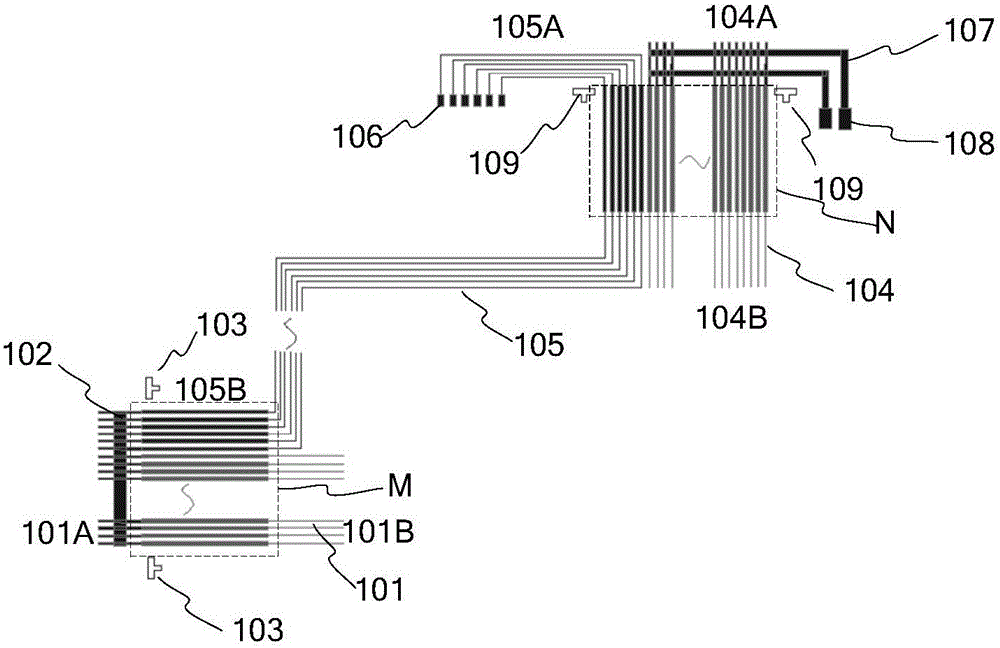
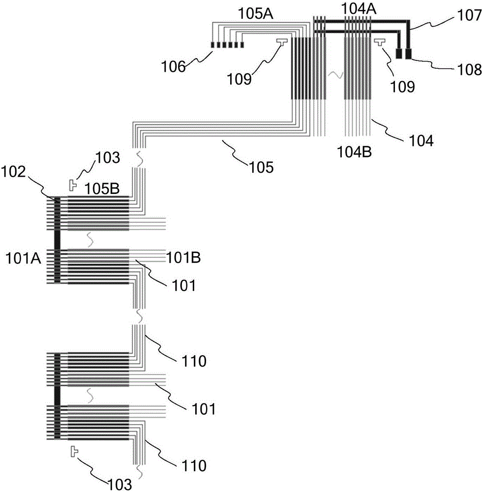
[0042] Such as figure 1 shown. An embodiment of the present invention provides a display panel test circuit, including: a plurality of gate test lines 101 corresponding ...


PUM


Abstract

The invention discloses a display panel test circuit, a display panel and a test method thereof. The display panel test circuit comprises a plurality of grid test lines in one-to-one correspondence with grid lines, wherein the output end of each grid test line is connected to the corresponding grid line; the input ends of the grid test lines are in short connection with each other; the extension direction of each grid test line is consistent with that of the corresponding grid line; the grid test lines are used for inputting grid test signals to the grid lines connected to the grid test lines during a test. Through the display panel test circuit provided by the embodiment of the invention, a large quantity of test modules and detection probes are saved; the grid test lines are in short connection with each other; a same grid test signal is input to each grid test line, so that the signal attenuation can be avoided; the display panel can be rapidly brightened; a test manner of inputting a plurality of test signals and scanning is replaced; the time for brightening the display panel is shortened, namely the test time is shortened.

Description

technical field [0001] The invention relates to the field of display technology, in particular to a display panel test circuit, a display panel and a test method thereof. Background technique [0002] At present, the production process of Thin Film Transistor Liquid Crystal Display (TFT-LCD) includes: bonding the prepared array substrate and color filter substrate together with a sealant to form a complete display panel, and then A detection circuit is used to detect the display panel. [0003] When testing the liquid crystal cell (Cell), it is necessary to use the test module (block) for testing. The test module loads signals on the signal lines in the connection (Lead) area of ​​the display panel through the detection probe contact (Block Pin Contact), and the detection probe The needles (Block Pins) correspond to the signal lines in the connection area one by one, and the distance between adjacent detection probes and adjacent signal lines is 38-40um. Due to the extreme...

Claims


Application Information

Patent Timeline
Patent Type & Authority Applications(China)
IPC IPC(8): G02F1/13G09G3/00
CPCG02F1/1309G09G3/006
Inventor 曹金虎历伟马明辉吴岩岩高棉曹斌权南仁于凤武
Owner BOE TECH GRP CO LTD
Why Eureka
Try Eureka