State estimation method for reactive power compensation device applied to utility tunnel

A compensation device and state estimation technology, applied in reactive power compensation, reactive power adjustment/elimination/compensation, etc., can solve problems such as impractical non-linear characteristics of devices and unmeasurable state vectors of control systems

Inactive Publication Date: 2016-09-07
WISDRI ENG & RES INC LTD
View PDF2 Cites 0 Cited by
  • Summary
  • Abstract
  • Description
  • Claims
  • Application Information

AI Technical Summary

Problems solved by technology

However, due to the physical limitations of the actual system, the state vector of the control system is often unmeasurable, and what is more unfavorable is that the nonlinear characteristics of the device itself also make the conventional state estimation method impractical

Method used


Image

  • State estimation method for reactive power compensation device applied to utility tunnel
  • State estimation method for reactive power compensation device applied to utility tunnel
  • State estimation method for reactive power compensation device applied to utility tunnel

Examples


Embodiment Construction

[0025] The present invention will be further described below in conjunction with specific examples and drawings.

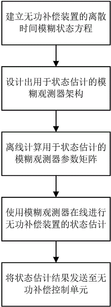
[0026] A state estimation method of reactive power compensation device applied to integrated pipe gallery, such as figure 1 As shown, it includes the following steps:

[0027] S1. Establish the discrete-time fuzzy state equation of the reactive power compensation device:

[0028] x ( k + 1 ) = X i = 1 r h i ( z ( k ) ) ( A i x ( k ) + B i u ( k ) ) y ( k ) = X i = 1 r h i ( z ( k ) ) C i x ( k ) ,

[0029] In the formula, x(k) is the state vector of the reactive power compensation device at time k, and the dimension is n 1 ×1; x(k+1) is the state vector of the reactive power compensation device at k+1, the dimension is n 1 ×1; u(k) is the input vector of the reactive power compensation device at time k, th...


PUM


Abstract

The invention provides a state estimation method for a reactive power compensation device applied to a utility tunnel. The method comprises the steps of establishing a discrete time fuzzy state equation of the reactive power compensation device; designing a fuzzy observer for state estimation; calculating a parameter matrix of the fuzzy observer for state estimation offline; carrying out state estimation on the reactive power compensation device online by use of the fuzzy observer; considering that the state estimation effect reaches an allowed range and sending a state estimation result x< ^ >(k) to a reactive power compensation control unit for follow-up reactive power compensation control when the absolute value of y(k)-y< ^ >(k) is less than epsilon, wherein the epsilon is a preset threshold value for judging whether to put the fuzzy observer into follow-up use or not. According to the method, the technical problem of nonlinear term processing in the physical system of the reactive power compensation device can be solved effectively.

Description

Technical field [0001] The invention belongs to the control system design field of a reactive power compensation device of a comprehensive pipe gallery, and specifically designs a state estimation method of a reactive power compensation device applied to a comprehensive pipe gallery. Background technique [0002] The TCR high-voltage static dynamic reactive power compensation device is widely used in municipal distribution networks such as high-voltage and ultra-high-voltage AC / DC transmission systems and integrated pipe corridors. Its main function is to improve the operating conditions of the power supply network, control power pollution, and improve transmission and distribution. The reliability of the electrical system can suppress system overvoltage, improve its dynamic characteristics, suppress harmonics, reduce the pollution and voltage flicker caused by harmonics to electric energy, stabilize system voltage, quickly track reactive power compensation, and improve power fact...

Claims


Application Information

Patent Timeline
Patent Type & Authority Applications(China)
IPC IPC(8): H02J3/18
CPCY02E40/30H02J3/18
Inventor 赵昊裔
Owner WISDRI ENG & RES INC LTD
Why Eureka
Try Eureka