
Magnet and actuator

A technology of magnets and permanent magnets, applied in the directions of magnets, electromagnets, magnetic objects, etc., can solve the problems of magnet failure, complex structure, damage, etc., and achieve the effect of demagnetization prevention and simple structure

Active Publication Date: 2016-09-14
IXTUR
View PDF7 Cites 14 Cited by
  • Summary
  • Abstract
  • Description
  • Claims
  • Application Information

AI Technical Summary

Problems solved by technology

In the first case, the disadvantage is the power consumption of the coils, while in the second it is the complex structure, which can be easily destroyed, leading to the failure of the magnets

Method used


Image

  • Magnet and actuator
  • Magnet and actuator
  • Magnet and actuator

Examples


Embodiment Construction

[0054] The same reference numerals are used for the same or similar parts in different embodiments.

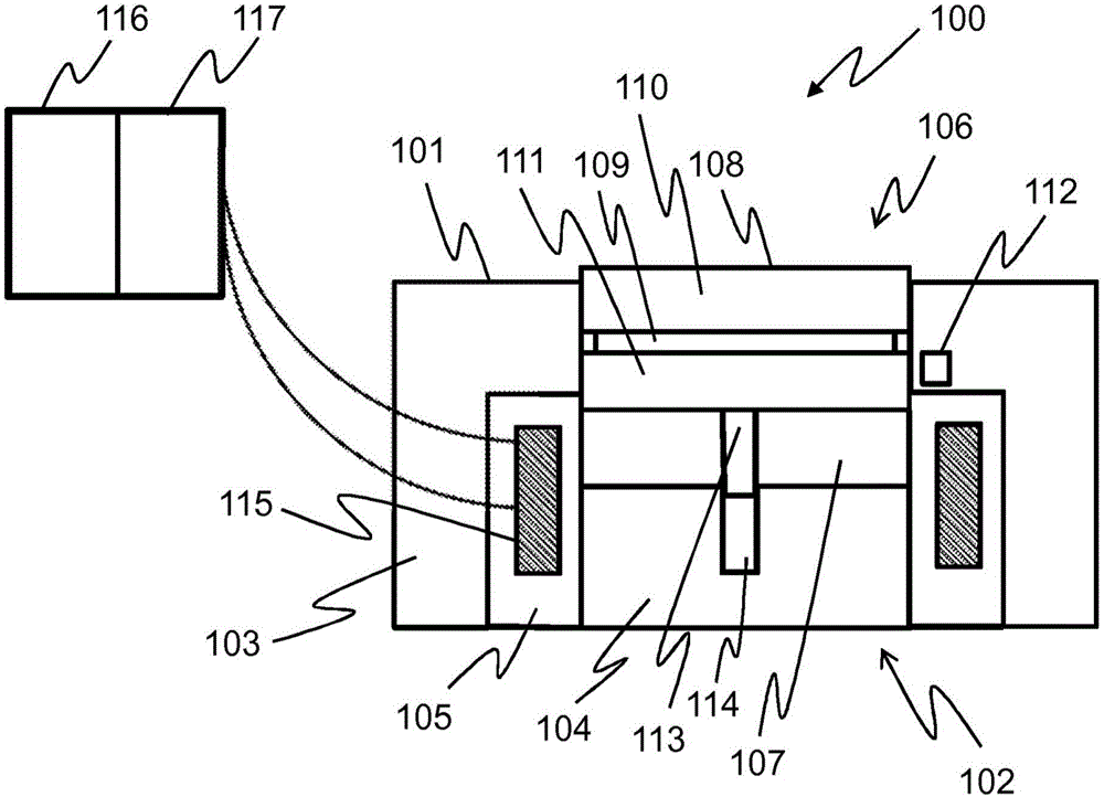
[0055] figure 1 A cross-sectional view of a magnet according to a first embodiment of the present invention is shown. The magnet 100 comprises a cylindrical body 101 comprising at one end thereof an attachment surface 102 intended to be arranged in contact with an object to be attached.

[0056] The body 101 of the magnet 100 comprises a first part 103 and a second part 104 made of magnetic material. The first part 103 and the second part 104 are attached together by a third part 105 of the body 101, which is made of a non-magnetic material. The third part 105 has the form of a sleeve and is attached around the cylindrical second part 104 . The first part 103 is attached around the third part 105 .

[0057] The first part 103 comprises a hole 106 leading to a first cavity 107 of the body 101, which is cylindrical. The bottom of the first cavity 107 is defined by the secon...


PUM


Abstract

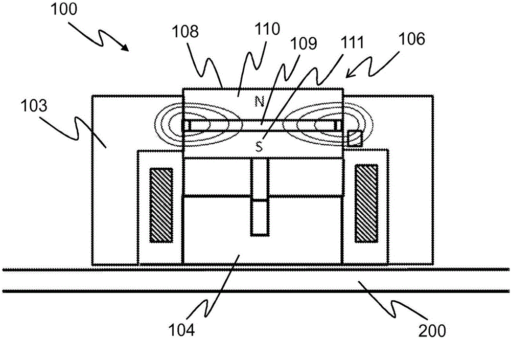
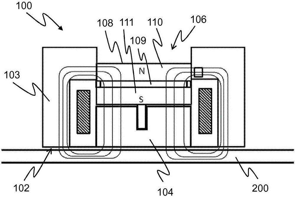
The present invention provides a magnet (100), which comprises a body (101) having a first and a second section (103, 104), and a slide (108) arranged to be movable relative to the body (101) between a first and a second position. The slide (108) comprises a permanent magnet (109), and a first and a second pole piece (110, 111) that are attached to opposite magnetic pole surfaces of the permanent magnet (109). The first section (103) comprises a hole (106) that opens into a first cavity (107) of the body (101), the bottom of the first cavity (107) being delimited at least partly by the second section (104). The slide (108) is movably arranged in the hole (106) so that the second pole piece (111) is directed towards the bottom of the first cavity (107), wherein at the first position of the slide (108), magnetic flux generated by the permanent magnet (109) is short-circuited by the first section (103), and at the second position of the slide (108), magnetic flux generated by the permanent magnet (109) is directed through the first and the second section (103, 104).

Description

technical field [0001] The invention relates to a magnet according to the preambles of the appended independent claims. Background technique [0002] Magnets are used in many technical fields to perform various operations such as controlling motions, switching electrical circuits and moving objects. A magnet usually has some function to change its magnetic state. The magnet may include, for example, a coil that generates a magnetic field according to the amount and direction of current supplied to the coil. Coils can be used alone or in combination with permanent magnets, so the coils are used to increase or decrease the magnetic field generated by the permanent magnets. Alternatively, the magnet may comprise a movable part, the position of which determines the magnetic state of the magnet. The movable part comprising the permanent magnet moves relative to the body of the magnet, eg following a magnetic force generated by a coil arranged to surround the movable part. [...

Claims


Application Information

Patent Timeline
Patent Type & Authority Applications(China)
IPC IPC(8): H01F7/02H01F7/04H01F7/16
CPCH01F7/0226H01F7/0252H01F7/0257H01F7/04H01F7/1615H01F2007/1669B66C1/04H01F7/0231H01F7/0268G01D5/12H01F7/0205H01H36/0006
Inventor 雷约·内蒂
Owner IXTUR
Learn More