
Automatic cooling and packaging device

An automatic cooling and packaging machine technology, applied in packaging and other directions, can solve the problems of slow cooling efficiency and need large space, and achieve the effect of improving heat dissipation efficiency and high efficiency

Inactive Publication Date: 2016-09-21
RUIJIA YIXING TECH
View PDF5 Cites 5 Cited by
  • Summary
  • Abstract
  • Description
  • Claims
  • Application Information

AI Technical Summary

Problems solved by technology

The cooling efficiency is slow and requires a lot of space. After cooling, collect them and continue to pack them

Method used


Image

  • Automatic cooling and packaging device

Examples


Embodiment Construction

[0009] The specific embodiment of the present invention will be described with reference to the accompanying drawings.

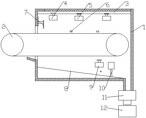
[0010] Such as figure 1 As shown, the automatic cooling packaging device includes a box body 1. There is a material inlet on one side of the box body 1, and a material outlet on the bottom of the other side. The top of the box body 1 is a ventilated roof; a conveyor belt 2 is installed at the material inlet. One end of 2 is outside the box body 1 for receiving materials, and the other end is located above the discharge port; there is a scraper 7 at the feed port, and the scraper 7 is installed in the box body 1 through a lifting device, and the scraper 7 Located above the conveyor belt 2; a cooling fan 4 is installed above the conveyor belt 2;

[0011] There is a slope 8 between the lower end of the feed inlet and the discharge port, a section of the discharge port is the low end, a spare heat dissipation fan 9 is arranged above the slope 8, and a spare sen...


PUM


Abstract

The invention relates to a chemical cooling device and particularly relates to an automatic cooling and packaging device. The automatic cooling and packaging device comprises a box body; a feeding hole is formed in one side of the box body; a discharging hole is formed in the bottom of the other side of the box body; the top of the box body is a ventilating top plate; a conveying belt is mounted at the feeding hole; one end of the conveying belt is outside the box body and is used for receiving a material; the other end of the conveying belt is positioned above the discharging hole; a scraping blade is arranged at the feeding hole and is mounted inside the box body through a lifting device; a cooling fan is also mounted above the conveying belt; a bevel is arranged between the lower end of the feeding hole and the discharging hole; one section of the discharging hole is a low end; a backup electric cooling fan is arranged above the bevel; a backup sensor is mounted below the backup electric cooling fan; a gate is arranged on the bevel; the lower portion of the discharging hole is connected with a discharged material weighing device; a packaging machine is arranged below the discharged material weighing device. The automatic cooling and packaging device has the advantages of improving the cooling efficiency by spreading the material, and realizing high efficiency by automatically monitoring the temperature of the material and regulating the cooling device for cooling; the material can be directly packaged without being taken down from a production line.

Description

technical field [0001] The invention relates to a chemical cooling device, in particular to an automatic cooling and packaging device. Background technique [0002] In chemical enterprises, after the preparation of some materials, it needs to be cooled to ensure that the traditional cooling includes natural cooling and medium cooling, and natural cooling is usually used for some granular substances. The cooling efficiency is slow and requires a lot of space. After cooling, the collection is collected and continues to be packaged. Contents of the invention [0003] In view of the above technical problems, the present invention provides a cooling device for particulate matter, which improves the cooling effect and realizes packaging on one production line at the same time. [0004] The specific technical solutions are: [0005] The automatic cooling packaging device includes a box body, with a material inlet on one side of the box body, a material outlet at the bottom of t...

Claims


Application Information

Patent Timeline
Patent Type & Authority Applications(China)
IPC IPC(8): B65B63/08
CPCB65B63/08
Inventor 林清华
Owner RUIJIA YIXING TECH
Learn More