A hollow self-expanding bottom anchor bolt and its installation method

An installation method and self-expanding technology, which can be used in the installation of bolts, earthwork drilling, sheet pile walls, etc., can solve problems such as poor bottom expansion effect, and achieve high reliability, good bottom expansion effect, and improved bottom expansion effect. Effect

Active Publication Date: 2018-01-09
WUDA JUCHENG STRUCTURE CO LTD
View PDF7 Cites 1 Cited by
  • Summary
  • Abstract
  • Description
  • Claims
  • Application Information

AI Technical Summary

Problems solved by technology

[0005] The purpose of the present invention is to overcome the defects and problems of poor bottom expansion effect existing in the prior art, and to provide a hollow self-expanding bottom anchor bolt with good bottom expansion effect and its installation method

Method used


Image

  • A hollow self-expanding bottom anchor bolt and its installation method
  • A hollow self-expanding bottom anchor bolt and its installation method
  • A hollow self-expanding bottom anchor bolt and its installation method

Examples


Embodiment 1

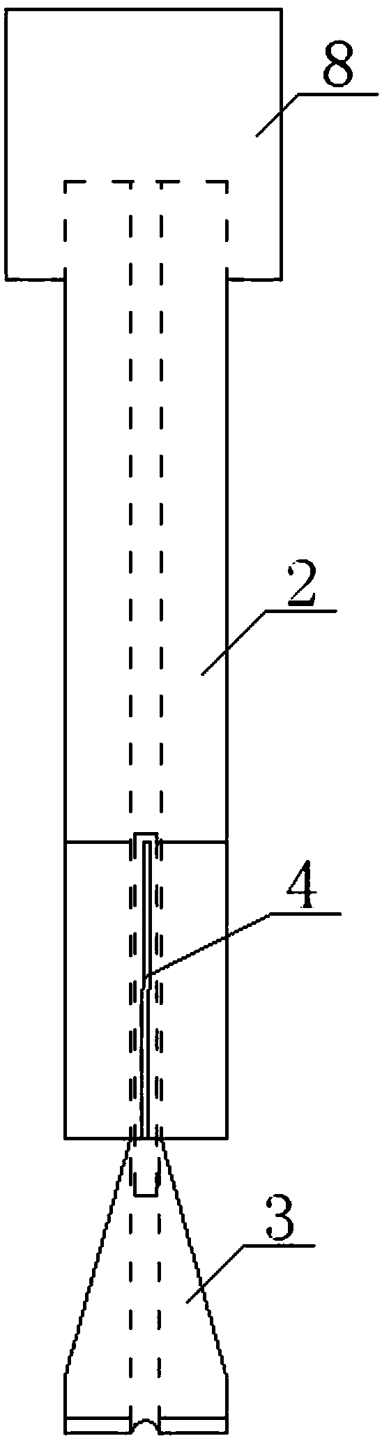
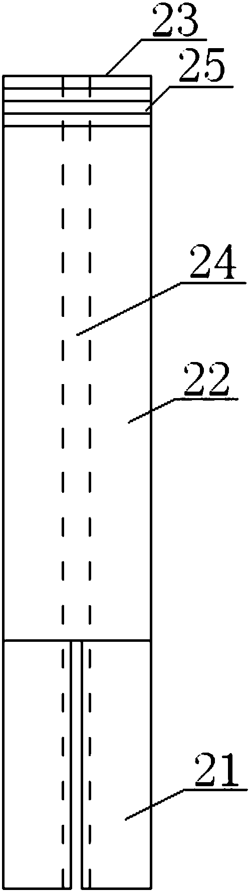
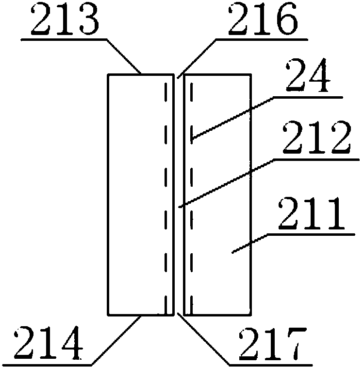
[0084] see Figure 1 to Figure 9 , a hollow self-expanding bottom anchor bolt, including a rod body 2, a wedge 3, and a liner pipe 4; the rod body 2 includes a bottom end 21, an intermediate rod 22, and an exposed end 23 connected in sequence; Rod inner hole 24, one end of the rod inner hole 24 extends to the end face of the exposed end 23, the other end of the rod inner hole 24 extends to the end face of the bottom end 21, the bottom end 21 includes a cutter head 211 and a slit 212, the number of the cutter head 211 is at least two, the cutter head 211 includes an upper end 213, a lower end 214, and an outer peripheral surface 215, the number of the slits 212 is equal to the number of the cutter heads 211, and the slits 212 are located at two adjacent Between two cutter heads 211, the slit 212 includes a first end 216, a second end 217, a third end 218, and a fourth end 219, the first end 216 extends to the end surface of the upper end 213, and the second end 217 extends On ...

Embodiment 2

[0089] Basic content is the same as embodiment 1, the difference is:

[0090] In terms of structure: the wedge head 31 is a regular pyramid structure. The wedge head 31 includes a wedge top 35 and a side edge 38. The wedge top 35 is in contact with the lower end 214. position, the taper angle 36 of the wedge head 31 is less than twice the friction angle between the two materials of the rod body 2 and the wedge block 3;

[0091] In step a: when the side edge 38 is located at the position facing the slit 212, the wedge top 35 is in contact with the lower end 214, and the outer peripheral surface of the other end of the lining pipe 4 is connected to the inner peripheral surface of the inner hole 24 of the rod, the insertion is stopped .

Embodiment 3

[0093] Basic content is the same as embodiment 1, the difference is:

[0094] In terms of structure: the wedge head 31 is a wedge structure, the wedge head 31 includes a wedge top 35 and a wedge surface 39, the wedge top 35 is in contact with the lower end 214, and the wedge surface 39 is located at a position facing the slit 212 , the taper angle 36 of the wedge head 31 is less than twice the friction angle between the two materials of the rod body 2 and the wedge block 3;

[0095] In step a: when the wedge surface 39 is located at the position facing the slit 212, the wedge top 35 is in contact with the lower end 214, and the outer peripheral surface of the other end of the lining pipe 4 is connected to the inner peripheral surface of the inner hole 24 of the rod, the insertion is stopped .


PUM


Abstract

A hollow self-expanding bottom anchor bolt, including a rod body, a wedge, and a liner pipe. The center of the rod body is provided with a hole in the rod body. The rod body includes a bottom end, a middle rod, and an exposed end. There is a wedge inner hole in the center of the center, the wedge includes a wedge head and a base, the outer peripheral surface of one end of the inner liner is connected with the inner peripheral surface of the inner hole of the rod, and the outer peripheral surface of the other end of the inner liner is connected with the inner hole of the wedge. The inner peripheral surface is connected, and the inside of the lining pipe is connected with the inner hole of the rod and the inner hole of the wedge; when installing, insert the above-mentioned anchor bolt into the bottom of the straight hole, hammer or impact the installation cap, so that the wedge pushes the cutter head toward the The hole wall is expanded, and the cutter head is inserted into the straight hole wall to chisel out the broken pieces. While hammering or impacting the installation cap, use the installation cap to input compressed air to blow out the broken pieces. The grout overflows, and the anchor bolts are installed after the grout solidifies. This design not only has good bottom expansion effect, but also has good grouting quality, high durability and high reliability.

Description

technical field [0001] The invention belongs to the technical fields of structural engineering anchorage, anchor bars connecting new and old structures, and foundation anchor bolts for equipment installation, and particularly relates to a hollow self-expanding bottom anchor bolt and an installation method thereof, which are mainly suitable for improving the bottom expansion effect. Background technique [0002] There are usually two anchoring methods for anchor bolts: one is mechanical anchoring, and the other is cemented anchoring. Mechanical anchoring mainly relies on the frictional resistance generated by the extrusion between the expansion head and the wall of the anchor hole to provide anchoring force. Due to the limited occlusal depth between the anchor head and the hole wall, the pullout resistance provided is not large, and the deformation of the hole wall and the relaxation of the expansion head easily cause the anchorage to fail and the reliability is low. The cem...

Claims


Application Information

Patent Timeline
Patent Type & Authority Patents(China)
IPC IPC(8): E02D5/74E21D21/00E02D5/80E21D20/02
CPCE02D5/74E02D5/808E21D20/021E21D21/0033
Inventor 周剑波高作平陈明祥张畅谭星舟
Owner WUDA JUCHENG STRUCTURE CO LTD
Why Eureka
Try Eureka