Tunnel ventilation structure and method
A tunnel ventilation and tunnel technology, which is used in mine/tunnel ventilation, earth-moving drilling, mining equipment, etc., can solve the problems of difficult maintenance, high fan cost and limited effect.
- Summary
- Abstract
- Description
- Claims
- Application Information
AI Technical Summary
Problems solved by technology
Method used
Image

Examples
Embodiment 1
[0036] Example 1: tunnel ventilation structure
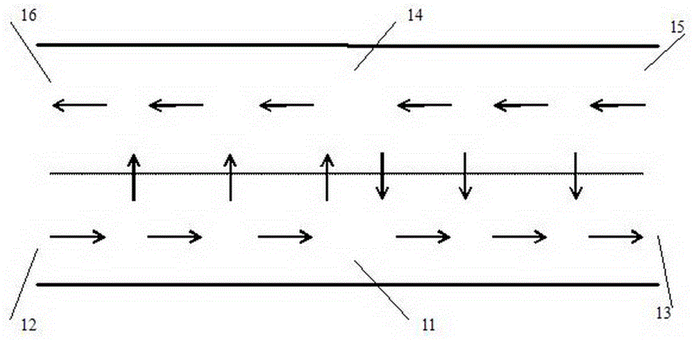
[0037] Such as figure 1 As shown, on the upway 11 of the tunnel, the overall movement direction of vehicles such as trains and automobiles or pedestrians is from left to right, so multiple or multiple groups of ejection devices are sequentially arranged on the upway 1, and the ejection devices The ejection direction is also from left to right, which is consistent with the movement direction of vehicles or pedestrians.
[0038] Equally, on the downway 14 of the tunnel, the overall movement direction of vehicles such as trains, automobiles or pedestrians is from left to right, then on this downway 14, a plurality or groups of ejection devices are sequentially set, and the ejection devices The ejection direction is also from left to right, which is consistent with the movement direction of vehicles or pedestrians.
[0039] Of course, as mentioned earlier, in figure 1 An arrow in the figure does not necessarily represent an injec...
Embodiment 2
[0040] Example 2: tunnel ventilation structure
[0041] Such as figure 1 As shown, on the upway 11 of the tunnel, the overall movement direction of vehicles such as trains and automobiles or pedestrians is from left to right, and then multiple or multiple groups of ejection devices are sequentially arranged on the upway 11, and the ejection devices The ejection direction is also from left to right, which is consistent with the movement direction of vehicles or pedestrians.
[0042] Equally, on the downway 14 of the tunnel, the overall motion direction of vehicles such as trains, automobiles or pedestrians is from right to left, then on this downway 14, a plurality or groups of ejecting devices are sequentially set, and the ejecting devices The ejection direction is also from left to right, which is consistent with the movement direction of vehicles or pedestrians.
[0043] Of course, as mentioned earlier, in figure 1 An arrow in the figure does not necessarily represent an ...
Embodiment 3
[0051] Embodiment 3: tunnel ventilation structure
[0052] Such as figure 1 As shown, on the upway 11 of the tunnel, the overall movement direction of vehicles such as trains and automobiles or pedestrians is from left to right, so multiple or multiple groups of ejection devices are sequentially arranged on the upway 1, and the ejection devices The ejection direction is also from left to right, which is consistent with the movement direction of vehicles or pedestrians.
[0053] Equally, on the downway 4 of the tunnel, the overall movement direction of vehicles such as trains, automobiles or pedestrians is from right to left, then on this downway 14, a plurality or groups of ejecting devices are sequentially set, and the ejecting devices The ejection direction is also from left to right, which is consistent with the movement direction of vehicles or pedestrians.
[0054] Of course, as mentioned earlier, in figure 1 An arrow in the figure does not necessarily represent an inj...
PUM
 Abstract
Description
Claims
Application Information
 - R&D
- Intellectual Property
- Life Sciences
- Materials
- Tech Scout
- Unparalleled Data Quality
- Higher Quality Content
- 60% Fewer Hallucinations
Browse by: Latest US Patents, China's latest patents, Technical Efficacy Thesaurus, Application Domain, Technology Topic, Popular Technical Reports.
© 2025 PatSnap. All rights reserved.Legal|Privacy policy|Modern Slavery Act Transparency Statement|Sitemap|About US| Contact US: help@patsnap.com