
Method for automatically identifying vehicle clutch signal

A clutch signal, automatic identification technology, applied in the direction of components with teeth, transmission control, belt/chain/gear, etc., can solve problems such as errors, and achieve the effect of accurate correction

Active Publication Date: 2016-09-21
XIAMEN YAXON NETWORKS CO LTD
View PDF8 Cites 2 Cited by
  • Summary
  • Abstract
  • Description
  • Claims
  • Application Information

AI Technical Summary

Problems solved by technology

Patent 201510602528.0 judges the clutch state by collecting the ratio of the engine speed and the output shaft speed of the gearbox. This method is prone to errors due to the measurement accuracy of the speed data

Method used


Image

  • Method for automatically identifying vehicle clutch signal
  • Method for automatically identifying vehicle clutch signal
  • Method for automatically identifying vehicle clutch signal

Examples


Embodiment Construction

[0023] In order to make the technical problems, technical solutions and beneficial effects to be solved by the present invention clearer and clearer, the present invention will be further described in detail below in conjunction with the accompanying drawings and embodiments. It should be understood that the specific embodiments described here are only used to explain the present invention, not to limit the present invention.

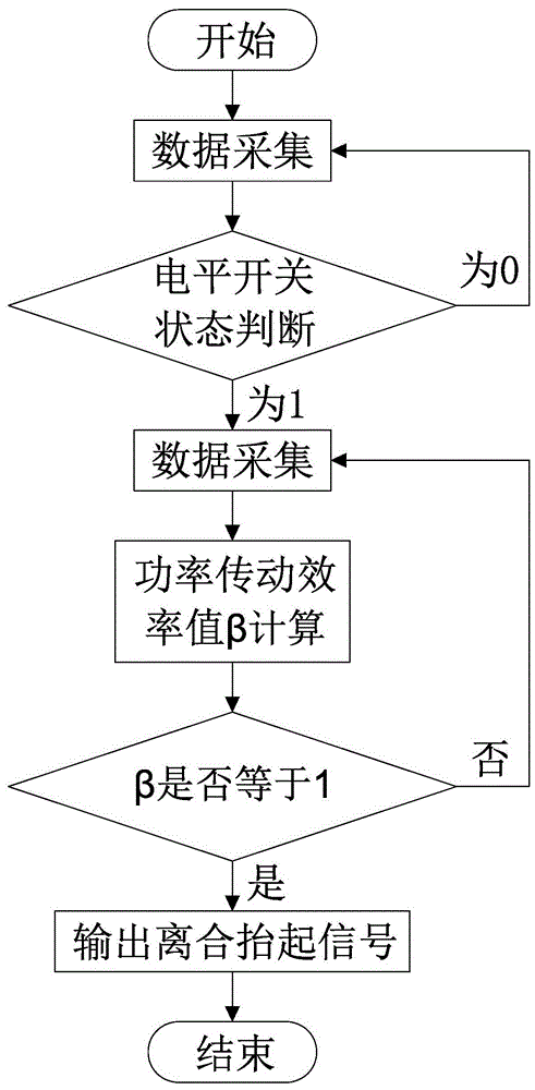
[0024] Such as figure 1 As shown, the automatic recognition method of a kind of vehicle clutch signal that the present invention discloses, it comprises the following steps:

[0025] S1. data collection, its steps include:

[0026] S11. Continuously collect data from the CAN bus of the vehicle with time T as the cycle, and record the data set collected each time {P j , u j , a j , t j}, where P j , u j , a j , t j They are the engine output power, vehicle speed, acceleration and collection time data collected for the jth time; the data set {P ...


PUM


Abstract

The invention discloses a method for automatically identifying a vehicle clutch signal. The method comprises the following procedures: S1, data acquisition; and S2, clutch identification. The procedure of data acquisition comprises the following steps: S11, constantly performing data acquisition on a vehicle CAN bus over a cycle of time T, and recording all the acquired data sets {Pj, uj, aj, tj}; and S12, performing judgement according to the clutch level switch state acquired in the latest data acquisition process. The procedure of clutch identification comprises the following steps: S21, after extracting a standard data set, proceeding with data acquisition on the vehicle CAN bus over the cycle of time T, and recording all the acquired data sets {Pj, uj, aj, tj}; S22, whenever acquiring a data set which follows the standard data set, calculating the current engine power transmission efficiency value beta once according to the acquired data P0, Pj, aj, a0, uj and m; and S23, judging the beta values calculated after every data acquisition. By adoption of the method disclosed by the invention, the impact of driving behavior on the clutch signal can be avoided, the accuracy of overall vehicle control can be improved, and the driving behavior of a driver can be corrected.

Description

technical field [0001] The invention relates to an automatic recognition method of a vehicle clutch signal. Background technique [0002] The vehicle clutch signal is an important signal that some control functions of the vehicle need to use. Its function is that the clutch state plays an important role in the vehicle engine management control system and is an important basis for engine torque control. However, in a car with manual transmission, the triggering of the clutch signal is often affected by the driver's bad driving behavior for the following reasons: [0003] The clutch signal of the existing vehicle is to trigger a level switch when the clutch pedal is fully lifted, and its value is 1 (the level switch is 1 when the clutch is lifted, and it is 0 when the clutch is depressed), so that the level output clutch lift signal. However, among drivers of large trucks and buses, due to the large force required to lift the clutch pedal, the driver feels that the clutch is...

Claims


Application Information

Patent Timeline
Patent Type & Authority Applications(China)
IPC IPC(8): F16H61/02
CPCF16H61/0202
Inventor 涂岩恺刘炯钟谭芳慧吕伟煌
Owner XIAMEN YAXON NETWORKS CO LTD
Learn More