Pneumatic grip

A gripping device and air pressure technology, applied to gymnastics equipment, sports accessories, etc., can solve the problems that blood donors are difficult to control the grasping strength, blood donors do not know the optimal frequency of grasping the gripping ball, etc., so as to increase the fun and improve pumping. Blood efficiency, the effect of improving work efficiency

Inactive Publication Date: 2018-05-15
GUANGDONG UNIV OF TECH
View PDF6 Cites 0 Cited by
  • Summary
  • Abstract
  • Description
  • Claims
  • Application Information

AI Technical Summary

Problems solved by technology

However, the traditional grip ball has the following defects during use: (1), it is difficult for the blood donor to control the grip strength; (2), the blood donor does not know the optimal frequency of gripping the grip ball

Method used


Image

  • Pneumatic grip
  • Pneumatic grip
  • Pneumatic grip

Examples


Embodiment Construction

[0028] Embodiments of the present invention will be further described in detail below in conjunction with the accompanying drawings.

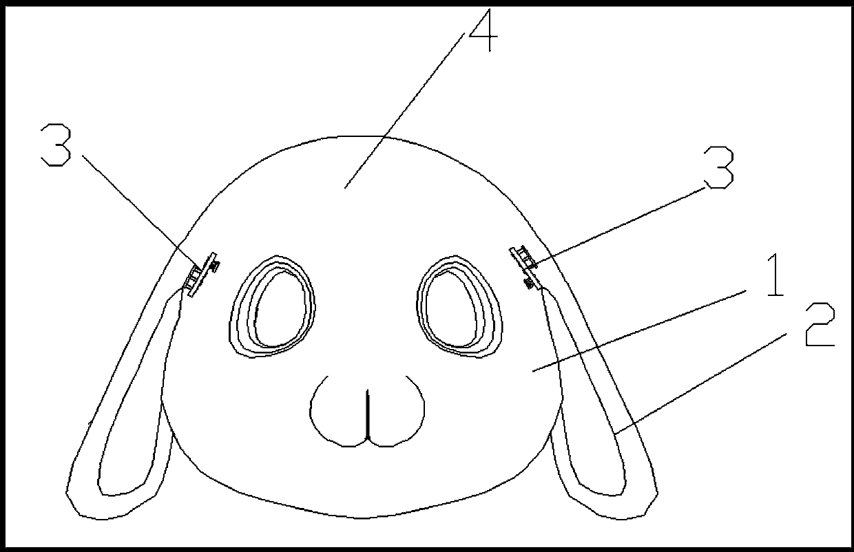
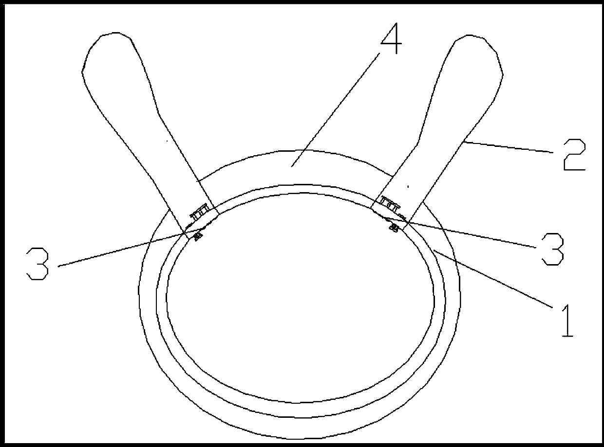
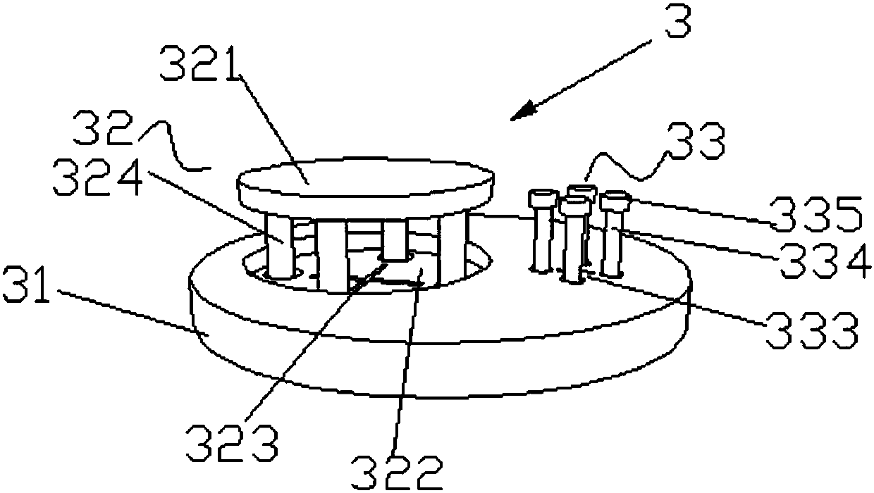
[0029] Such as Figure 1 to Figure 4 As shown, the air pressure grip includes an elastic cavity 1 and a telescopic cavity 2 integrally connected with the elastic cavity 1. The number of the telescopic cavity 2 is two symmetrically arranged on both sides of the elastic cavity 1. The telescopic cavity 2 and the elastic cavity The body 1 is separated by an exhaust mechanism 3 to form two independent airtight chambers;

[0030] When the force value of holding the elastic chamber 1 reaches the set value, the air flow passes through the exhaust mechanism 3 and enters the telescopic chamber 2 from the elastic chamber 1 and makes the telescopic chamber 2 bounce upward; When the force value is less than the set value, the air flow enters the elastic cavity 1 from the telescopic cavity 2 through the exhaust mechanism 3 and resets the telescopic cavity 2...


PUM


Abstract

The invention discloses an air pressure gripping force device. The air pressure gripping force device comprises an elastic cavity and a contraction cavity integrally connected with the elastic cavity, and two independent closed cavities which are separated by an exhaust mechanism are formed between the contraction cavity and the elastic cavity; when a value of force applied when the elastic cavity is gripped reaches a set value, air flow enters the contraction cavity from the elastic cavity through the exhaust mechanism and enables the contraction cavity to bounce upwards; when the value of the force applied when the elastic cavity is gripped is smaller than the set value, the air flow enters the elastic cavity from the contraction cavity through the exhaust mechanism and enables the contraction cavity to downwards reset. According to the air pressure gripping force device, the air flow flows back and forth between the elastic cavity and the contraction cavity by adopting the exhaust mechanism, whether the contraction cavity is caused to completely bounce or not is taken as a prompt signal, whether the gripping strength of a person subjected to blood drawing is appropriate or not is visualized, and therefore the person subjected to blood drawing can regulate the strength timely; the time interval that the contraction cavity resets again is taken as the gripping frequency, the person subjected to blood drawing is guided to accurately give out the force, therefore, vasospasm is avoided, and the blood drawing efficiency of a hospital is improved.

Description

technical field [0001] The invention relates to the field of medical aids, in particular to an air pressure gripper, which is mainly used for assisting blood drawing. Background technique [0002] When donating blood, in order to speed up the blood flow when drawing blood and prevent vasospasm, the staff usually provides a grip ball to the blood donor. Existing grip balls are mainly circular or egg-shaped balls made of highly elastic materials such as PU. After the blood donor grasps the grip ball, due to the effect of its high-elastic material, the grip ball will rebound quickly, and the blood donor can feel the pressure of the grip ball on the fingers. Generally, you can feel numbness and heat in the palm of your hand after grasping it several times. This is because the grip ball can effectively stimulate the various acupoints on the palm when the palm is continuously grasped, thereby promoting blood circulation, speeding up blood flow and The effect of preventing vasosp...

Claims


Application Information

Patent Timeline
Patent Type & Authority Patents(China)
IPC IPC(8): A63B23/16
CPCA63B23/16
Inventor 胡飞潘莉雷潇楚周园洪奔湉
Owner GUANGDONG UNIV OF TECH
Why Eureka
Try Eureka