Hydraulic wrist developer

A technology of gripper and hydraulic buffer, which is applied in the direction of equipment for compressing reflex points, physical therapy, etc., can solve the problems that blood donors do not know the optimal frequency of gripping the grip ball, and it is difficult for blood donors to control the grip strength, etc., to achieve increased Fun, prevent vasospasm, improve blood pumping efficiency

Inactive Publication Date: 2016-08-24
GUANGDONG UNIV OF TECH
View PDF5 Cites 2 Cited by
  • Summary
  • Abstract
  • Description
  • Claims
  • Application Information

AI Technical Summary

Problems solved by technology

However, the traditional grip ball has the following defects during use: (1), it is difficult for the blood donor to control the grip strength; (2), the blood donor does not know the optimal frequency of gripping the grip ball

Method used


Image

  • Hydraulic wrist developer
  • Hydraulic wrist developer

Examples


Embodiment Construction

[0022] Embodiments of the present invention will be further described in detail below in conjunction with the accompanying drawings.

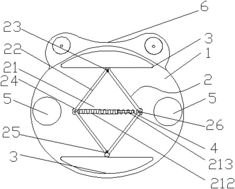
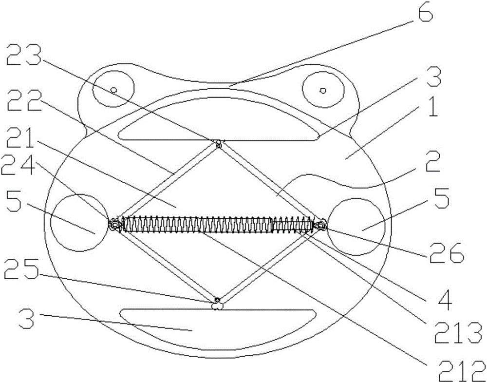
[0023] A hydraulic grip. The hydraulic grip includes an elastic cavity 1. The material of the elastic cavity 1 is silica gel, which can be rubber. There is a signal control assembly (the signal control assembly is the prior art, not shown in the figure) and a force applying mechanism 2 for opening or closing the signal control assembly. The signal control assembly is used to control the switch of the prompt signal.

[0024] The force application structure 2 includes a hydraulic buffer 21 and a force-bearing bracket 22. The four sides of the force-bearing bracket 22 are connected to each other through hinge shafts, and the diagonal first hinge shaft 23 and the third hinge shaft 25 are respectively fixed in the elastic cavity 1, the opposite second hinge shaft 24 and fourth hinge shaft 26 are respectively connected to the two ends of the hydrauli...


PUM


Abstract

The invention discloses a hydraulic wrist developer. The hydraulic wrist developer comprises an elastic cavity, a signal control assembly arranged in the elastic cavity, and a force application mechanism used for switching on or off the signal control assembly. The signal control assembly controls switch-on and switch-off of a prompt signal. The force application mechanism comprises a hydraulic buffer, a reset spring and a stress support. According to the hydraulic wrist developer, light emitted by a vibrating light-emitting diode is adopted as the prompt signal, whether the grasping force of a blood donor is proper or not is visible, and the blood donor can timely adjust the force; the interval at which the reset spring drives a buffer rod of the hydraulic buffer to slowly retract is adopted as the frequency at which the blood donor grasps the wrist developer, thus, the blood donor can accurately apply force, vasospasm is avoided, and the blood drawing efficiency in a hospital is improved.

Description

technical field [0001] The invention relates to the field of medical aids, in particular to a hydraulic gripper, which is mainly used to assist blood drawing. Background technique [0002] When donating blood, in order to speed up the blood flow when drawing blood and prevent vasospasm, the staff usually provides a grip ball to the blood donor. Existing grip balls are mainly circular or egg-shaped balls made of highly elastic materials such as PU. After the blood donor grasps the grip ball, due to the effect of its high-elastic material, the grip ball will rebound quickly, and the blood donor can feel the pressure of the grip ball on the fingers. Generally, you can feel numbness and heat in the palm of your hand after grasping it several times. This is because the grip ball can effectively stimulate the various acupoints on the palm when the palm is continuously grasped, thereby promoting blood circulation, speeding up blood flow and The effect of preventing vasospasm. Ho...

Claims


Application Information

Patent Timeline
Patent Type & Authority Applications(China)
IPC IPC(8): A61H39/04
CPCA61H39/04A61H2205/065
Inventor 潘莉胡飞周园洪奔湉雷潇楚
Owner GUANGDONG UNIV OF TECH
Why Eureka
Try Eureka