
Drive Structure of Piezoelectric Injector

A technology of drive structure and oiler, applied in piezoelectric effect/electrostrictive or magnetostrictive motors, machines/engines, generators/motors, etc., can solve the problem of reducing the performance and life of actuators, and the charging current is not easy to be high Accuracy control, can not guarantee the accuracy of the injector and other issues, to achieve the effect of benefiting stability and improving EMC capability

Active Publication Date: 2017-12-08
CHINA FAW LIMITED WUXI FUEL INJECTIONEQUIP RES INST +1
View PDF7 Cites 0 Cited by
  • Summary
  • Abstract
  • Description
  • Claims
  • Application Information

AI Technical Summary

Problems solved by technology

[0005] Since the charging voltage of the capacitor rises exponentially, the topological structure of the circuit presents a highly discrete nature. In addition, under complex working conditions, the dielectric parameters of the piezoelectric actuator change, making the charging current difficult to control with high precision; generally through The PWM-type switch realizes the charging and discharging structure of the actuator. On the one hand, it has high requirements on the inductive energy storage of the charging and discharging inductance. On the other hand, it cannot guarantee the consistency of the slope of the driving voltage, that is, the opening time of the injector cannot be guaranteed. Accuracy; In addition, the impact of peak current on the actuator may reduce the performance and life of the actuator

Method used


Image

  • Drive Structure of Piezoelectric Injector
  • Drive Structure of Piezoelectric Injector
  • Drive Structure of Piezoelectric Injector

Examples


Embodiment Construction

[0023] The present invention will be further described below in conjunction with specific drawings.

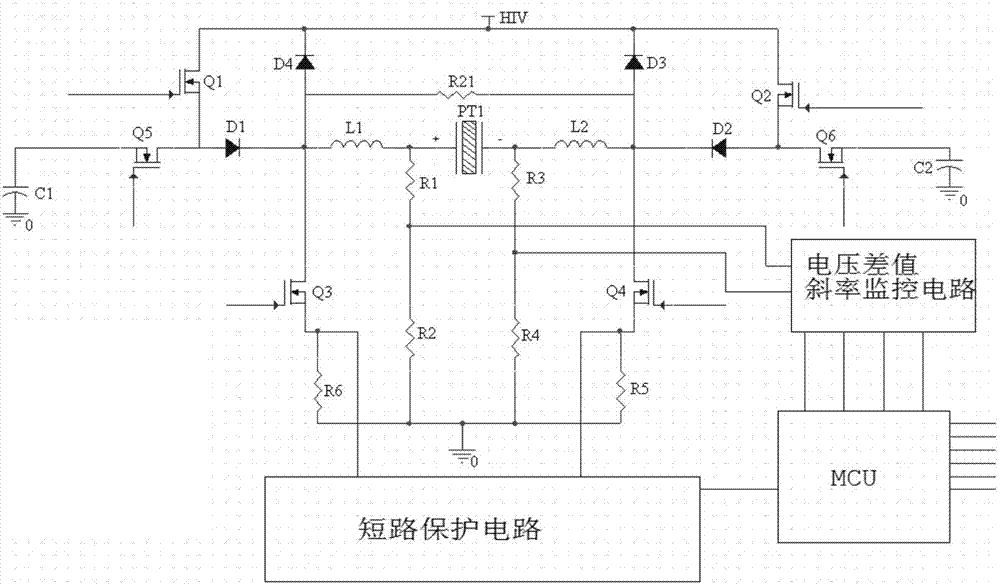
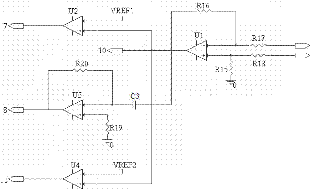
[0024] Such as figure 1 As shown, the present invention includes an actuator drive circuit module, a processor MCU, a voltage difference slope monitoring circuit and a short circuit protection circuit;

[0025] The actuator drive circuit module includes an actuator PT1, the high-voltage end of the actuator PT1 is connected to one end of the inductor L1 and one end of the resistor R1, and the other end of the inductor L1 is connected to the cathode end of the diode D1, the anode end of the diode D4, and the switching tube The drain terminal of Q3 is connected to one end of the resistor R21, the anode terminal of the diode D1 is connected to the source terminal of the switch tube Q1 and the drain terminal of the switch tube Q5, and the drain terminal of the switch tube Q1 is connected to the high voltage source HIV and the cathode terminal of the diode D4, The source end of the...


PUM


Abstract

The invention relates to a driving structure of a piezoelectric fuel injector. The driving structure is characterized by including an actuator driving circuit module, a processor MCU, a voltage difference value gradient monitoring circuit and a short circuit protection circuit. A driving voltage difference is formed by simultaneously charging and discharging the high and low ends of the actuator by means of the voltage non-mutation feature of a capacitor, namely, a voltage difference is formed by taking the voltage at the high end of the actuator as the reference voltage to control the discharging of the low end. During the establishment of driving, the voltage difference slope of the high end and the low end of the capacitor is determined by an external capacitance compensation means to control the current accuracy. The driving structure facilitates the stability of driving current and has no sensing value energy storage requirement on the filtering inductance of a driving circuit; and in addition, the current has no multi-peak-value oscillation, and the EMC capability of the system is improved.

Description

technical field [0001] The invention relates to a driving structure of a piezoelectric fuel injector, which belongs to the technical field of electronic control of fuel injectors of a common rail system. Background technique [0002] The piezoelectric drive in foreign patents is based on the charging and discharging structure of the linear regulator mode, such as US20090038590AI or US7819337B2 of DESN Company, that is, the high-voltage source is charged to the high-end of the actuator, and then the high-end of the actuator is discharged to the ground. The whole process is controlled by The voltage and current feedback control the PWM switch of the high-end switching tube to control the high-end voltage of the actuator, and the low-end forms a gating loop to the ground through the gating circuit. This structure has great energy storage requirements for the energy storage inductance, and due to the discrete nature of the parameters in the driving structure, the slope and accur...

Claims


Application Information

Patent Timeline
Patent Type & Authority Patents(China)
IPC IPC(8): H02N2/00F02M51/06
CPCF02M51/0603H02N2/0075
Inventor 高崴曾伟张爱云谢宏斌俞谢斌黄城健周维蒋诚丁珏
Owner CHINA FAW LIMITED WUXI FUEL INJECTIONEQUIP RES INST
Learn More