Camera and terminal device

A camera and camera device technology, applied in the electronic field, can solve problems such as the inability to flexibly adjust the working status of the flash

Inactive Publication Date: 2016-10-05
GUANGDONG OPPO MOBILE TELECOMM CORP LTD
View PDF4 Cites 24 Cited by
  • Summary
  • Abstract
  • Description
  • Claims
  • Application Information

AI Technical Summary

Problems solved by technology

The flashlight in the prior art cooperates with the camera, and the position and state of the flashlight have been fixed. When the user uses this camera device to take pictures, as long as the user chooses to turn on the flashlight, the working state of the flashlight has been determined, and the user cannot flexibly adjust the work of the flashlight. state

Method used


Image

  • Camera and terminal device
  • Camera and terminal device
  • Camera and terminal device

Examples


Embodiment Construction

[0023] Embodiments of the present application are described in detail below, examples of which are shown in the drawings, wherein the same or similar reference numerals denote the same or similar elements or elements having the same or similar functions throughout. The embodiments described below by referring to the figures are exemplary, and are intended to explain the present application, and should not be construed as limiting the present application. The camera and the terminal device according to the embodiments of the present application are described below with reference to the accompanying drawings.

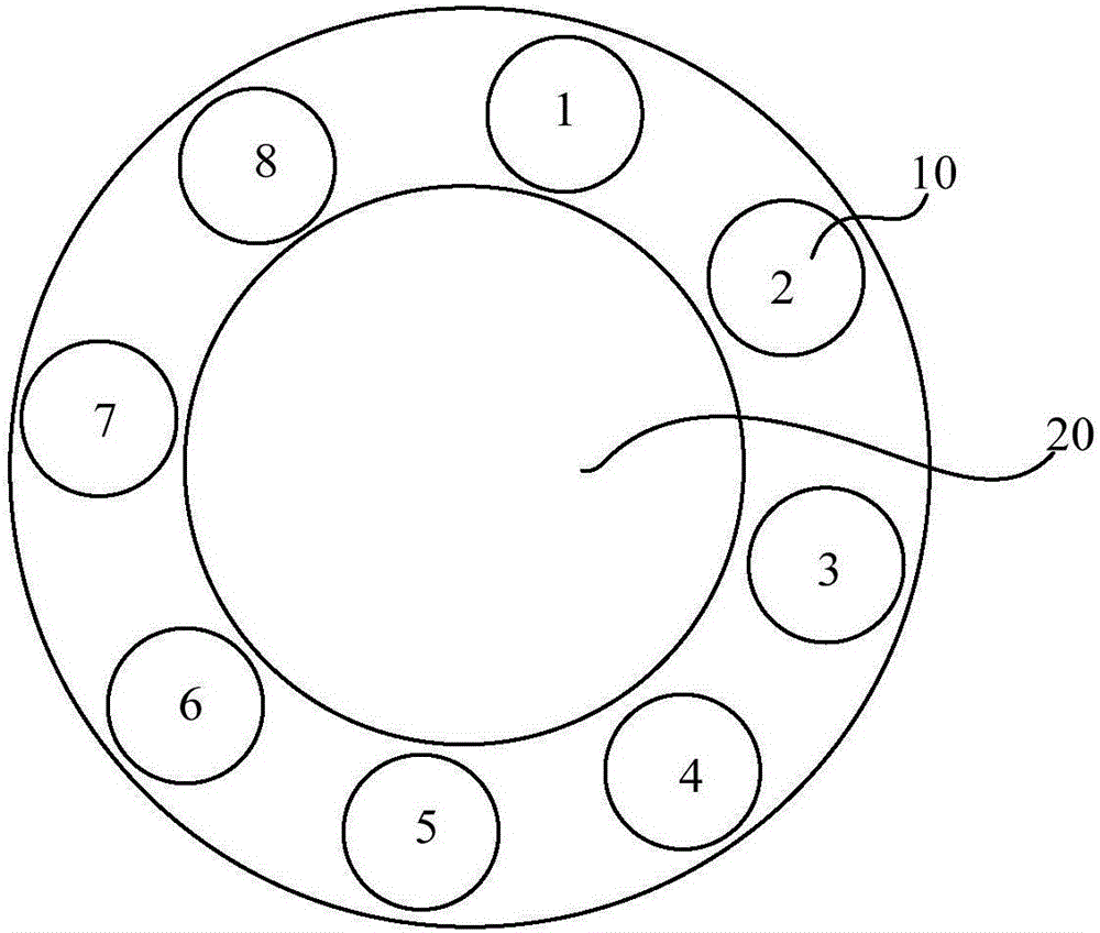
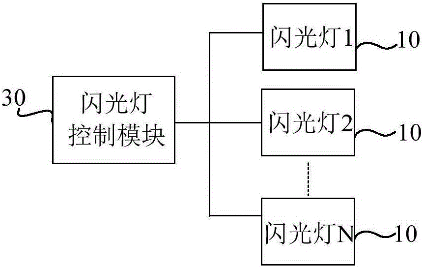
[0024] figure 1 is a schematic structural diagram of a camera according to an embodiment of the present application; figure 2 It is a control schematic diagram of a flashlight control module and multiple flashlights in an embodiment of the present application.

[0025] The camera 100 provided in this embodiment includes a plurality of flashlights 10, a lens module 20, ...


PUM


Abstract

The invention provides a camera and a terminal device. The camera comprises multiple flash lamps, a lens module and a flash lamp control module. the flash lamp control module is used for acquiring control information of a target flash lamp corresponding to the current photographing mode according to a preset control strategy and controlling the working state of the target flash lamp according to the control information. Thus, the working state of the flash lamp can be flexibly controlled.

Description

technical field [0001] The present application relates to the field of electronic technology, in particular to a camera and a terminal device. Background technique [0002] A flash is a photographic accessory that emits strong light in a short period of time. As one of the ways to enhance the exposure, turning on the flash helps to make the object being photographed brighter in a dark shooting environment. The flashlight in the prior art cooperates with the camera, and the position and state of the flashlight have been fixed. When the user uses this camera device to take pictures, as long as the user chooses to turn on the flashlight, the working state of the flashlight has been determined, and the user cannot flexibly adjust the work of the flashlight. state. Contents of the invention [0003] This application aims to solve one of the technical problems in the related art at least to a certain extent. [0004] Therefore, the purpose of this application is to propose a c...

Claims


Application Information

Patent Timeline
Patent Type & Authority Applications(China)
IPC IPC(8): H04M1/725H04N5/225H04N5/232H04N5/235
CPCH04M1/72403H04N23/57H04N23/55H04N23/667H04N23/74
Inventor 吴磊
Owner GUANGDONG OPPO MOBILE TELECOMM CORP LTD
Why Eureka
Try Eureka