Fan lamp with good lighting effect

A lighting effect and fan lamp technology, which is applied to the parts of lighting devices, lighting devices, lighting devices, etc., can solve the problem of the unsatisfactory light transmittance of the surrounding frame and the ring cover, the single structure and shape of the fan lamp, and the human body is prone to dizziness. It can achieve the effect of novel and unique structural design and light distribution method, convenient and quick installation and disassembly, and various lighting angles.

Pending Publication Date: 2019-03-29
危燕妮
View PDF0 Cites 1 Cited by
  • Summary
  • Abstract
  • Description
  • Claims
  • Application Information

AI Technical Summary

Problems solved by technology

With the improvement of people's living standards, fan lamps with poor functions and limited practicability are difficult to meet people's daily needs; and the fan lamps currently on the market have a single structure and shape, cumbersome assembly and installation, and traditional structural design and light distribution methods. , the illuminant is generally installed inside the fan body, the light transmittance of the frame and the ring cover is not ideal, the lighting effect is not good, and even the shadow of the fan blades shaking on the ground makes the human body prone to dizziness, and it cannot be used according to the actual situation. Adjust the lighting angle; once it is broken, the entire fan lamp cannot be illuminated, and it needs to be repaired and replaced, which is extremely inconvenient, and it is troublesome to disassemble retrogradely, and it is difficult to repair and maintain, which is not conducive to market promotion and low practicability

Method used


Image

  • Fan lamp with good lighting effect
  • Fan lamp with good lighting effect
  • Fan lamp with good lighting effect

Examples


Embodiment Construction

[0020] It should be understood that the specific embodiments described here are only used to explain the present invention, not to limit the present invention.

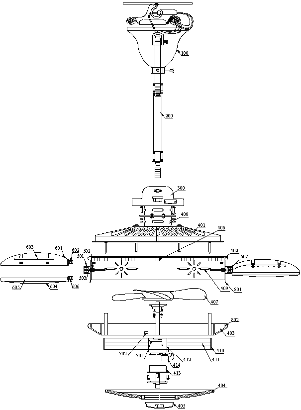
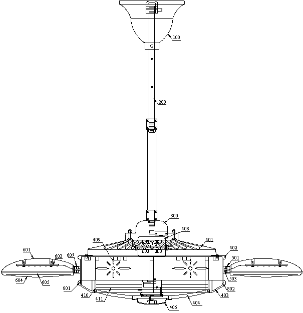
[0021] refer to Figure 1 to Figure 4 , propose an embodiment of a fan lamp with good lighting effect according to the present invention, which includes a fixed base 100, a telescopic rod 200 fixed on the lower end of the fixed base 100 and stretchable so as to adjust the height of the fan lamp, and a fixed base from top to bottom. The back cover 300 arranged at the lower end of the telescopic rod 200 and the fan body fixed on the back cover 300 . The fixing base 100 can conveniently fix the fan light on the ceiling, and at the same time, the telescopic rod 200 extending at the lower end of the fixing base 100 can be stretched up and down so that the height of the fan light can be freely adjusted to meet the different needs of different customers. The structure is simple and the operation is convenient .

[0022] Th...


PUM


Abstract

The invention discloses a fan lamp with a good lighting effect. The fan lamp comprises a fixed seat, a telescopic rod, a rear cover and a fan body, wherein the fan body sequentially comprises a rear net cover, a surrounding frame, a ring cover, a front net cover and an end cover from top to bottom; the fan lamp further comprises a rotating shaft, fan blades fixedly arranged on the rotating shaft,a main motor arranged in the rear cover and capable of driving the rotating shaft to rotate; a plurality of mounting screw holes are uniformly distributed in the outer side wall of the surrounding frame; and a lamp holder structure is fixedly arranged on the mounting screw holes; and the fan lamp further comprises a luminous body, wherein the luminous body is embedded in the lamp holder structurein a clamping connection mode and capable of rotating and adjusting the lighting angle by 360 degrees. The fan lamp integrates various functions of a fan, illumination, air purification, health care and the like and has a simple structure, reasonable design, unique shape and various functions, the luminous body is arranged outside the fan body and can adjust the illumination angle by 360 degrees,the illumination effect is good, the flexibility is high, the structural design and light distribution mode are novel and unique, the practicability is high, installation and disassembly are convenient and quick, and the later maintenance is simple.

Description

technical field [0001] The invention relates to the technical field of lamps, in particular to a fan lamp with good lighting effect. Background technique [0002] Fan lights, as the name implies, combine fans and lights into a new product, which is widely used in interior decoration lighting. With the improvement of people's living standards, fan lamps with poor functions and limited practicability are difficult to meet people's daily needs; and the fan lamps currently on the market have a single structure and shape, cumbersome assembly and installation, and traditional structural design and light distribution methods. , the illuminant is generally installed inside the fan body, the light transmittance of the frame and the ring cover is not ideal, the lighting effect is not good, and even the shadow of the fan blades shaking on the ground makes the human body prone to dizziness, and it cannot be used according to the actual situation. Adjust the lighting angle; once broken,...

Claims


Application Information

Patent Timeline
Patent Type & Authority Applications(China)
IPC IPC(8): F21S8/06F21V17/12F21V21/30F21V33/00F24F3/16
CPCF21S8/063F21V17/12F21V21/30F21V33/0096F24F3/16F21Y2115/10F24F8/30
Inventor 危燕妮
Owner 危燕妮
Why Eureka
Try Eureka