Household illuminating lamp and household illuminating lamp control method

A technology for lighting and home use, which is applied in the field of lighting, and can solve problems such as discounting the environmental quality of lighting and affecting user experience

Pending Publication Date: 2020-07-07
ETI SOLID STATE LIGHTING ZHUHAI LTD
View PDF0 Cites 1 Cited by
  • Summary
  • Abstract
  • Description
  • Claims
  • Application Information

AI Technical Summary

Problems solved by technology

[0003] For traditional lights, the user's requirements for light comfort are often ignored, and the environmental quality of the lights is greatly reduced, which affects the user's experience

Method used


Image

  • Household illuminating lamp and household illuminating lamp control method
  • Household illuminating lamp and household illuminating lamp control method
  • Household illuminating lamp and household illuminating lamp control method

Examples


Embodiment 1

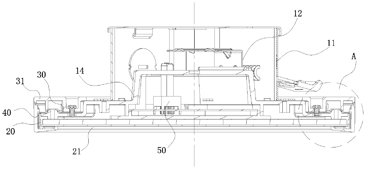
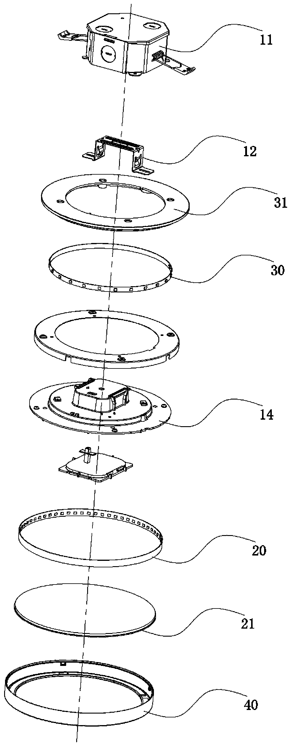
[0039] Such as Figure 1 to Figure 3 As shown, a household lighting lamp. The household lighting lamp in this embodiment is a downlight, which includes a lamp holder formed by fixed connection of a mounting bracket 11, a ceiling mounting bracket 12, and a chassis 14. The front side of the chassis 14 is a front panel , the rear side of the lamp holder is an installation part, which is used to install and fix the lighting lamp.

[0040] The front of the chassis 14 is provided with a light-guiding member 21 composed of a three-piece set of light guides, and a main light source 20 is arranged on the lateral edge of the light-guiding member 21 (that is, a light band is used to surround the light-guiding member 21 . Circumferential sides), a frame 40 is provided on the circumferential outer side of the main light source 20 .

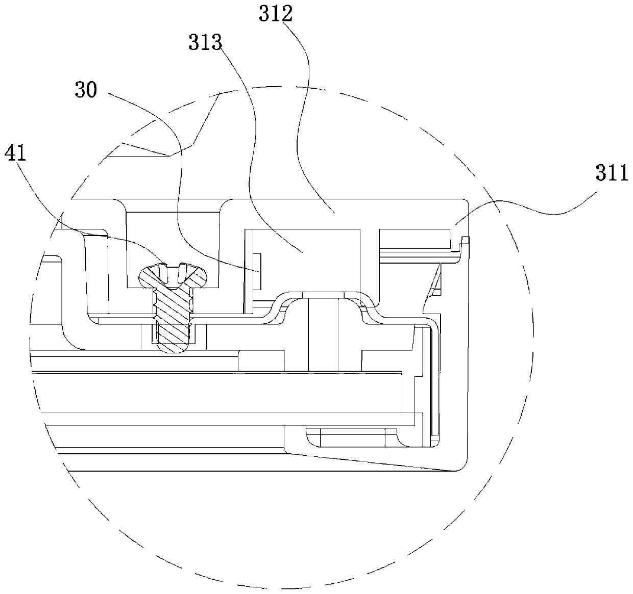
[0041] The annular cover plate on the rear side of the chassis 14, the annular cover plate is a secondary light guide 31, and an annular groove 313 is arrang...

Embodiment 2

[0052] Such as Figure 4 , Figure 5 As shown, the household lighting lamp described in this embodiment is a ceiling lamp. In this embodiment, it includes a lamp holder formed by fixedly connecting the lamp panel 13 and the chassis 14. The lamp panel 13 is used to install and fix the lighting lamp on the wall.

[0053] A ring platform 141 is arranged on the rear side of the chassis 14. The outer circumference of the ring platform 141 has a circumferential side wall 1411, and a heat dissipation frame 142 is arranged on the circumferential side wall 1411. The secondary light source 30 is a light strip. The tape is wound on the heat dissipation frame 142 of the circumferential side wall 1411 , and the secondary light guide member 31 is a light guide ring, and is clamped on the outer side of the circumferential side wall 1411 .

[0054] The principles and advantages of this embodiment are the same as those of Embodiment 1, and will not be repeated here.

[0055] In the aforement...


PUM


Abstract

The invention discloses a household illuminating lamp and a household illuminating lamp control method. The household illuminating lamp comprises a lamp holder, a main light-emitting component and a secondary light-emitting component; a front panel is arranged on the front side of the lamp holder, an installation part is arranged on the rear side of the lamp holder, the main light-emitting component is arranged in front of the lamp holder, the secondary light-emitting component is arranged behind and / or on the side of the lamp holder, and the main light-emitting component and the secondary light-emitting component are electrically connected with a control circuit. According to the invention, the illumination of the illuminating lamp can be conveniently adjusted, the light sensation comfortlevel is good, and the requirements of users for different scenes can be met.

Description

technical field [0001] The invention belongs to the field of lighting, and in particular relates to a household lighting lamp and a control method for the household lighting lamp. Background technique [0002] In the field of home decoration, household lighting has gone far beyond ordinary lighting functions. While satisfying basic lighting functions, people also need to consider the application scenarios of lighting and the user's pursuit of light sensitivity and comfort. [0003] For traditional lighting lamps, the user's requirements for light comfort are often ignored, which greatly reduces the environmental quality of the lighting lamps and affects the user experience. Contents of the invention [0004] The object of the present invention is to provide a household lighting lamp and a control method for the household lighting lamp. The invention can conveniently adjust the illumination of the lighting lamp, has good light comfort, and can adapt to the needs of users in...

Claims


Application Information

Patent Timeline
Patent Type & Authority Applications(China)
IPC IPC(8): F21S8/00F21V23/04F21V8/00
CPCF21S8/00F21V23/04G02B6/0076G02B6/0068G02B6/0028G02B6/0083G02B6/0086F21S8/026F21V23/0435F21Y2115/10F21Y2103/33F21Y2113/00G02B6/0073
Inventor 李廷宏招财武吴威威
Owner ETI SOLID STATE LIGHTING ZHUHAI LTD
Why Eureka
Try Eureka