
Manufacturing method of crankshaft

A manufacturing method and crankshaft technology are applied in the field of crankshaft manufacturing and can solve problems such as difficulty in crankshaft manufacturing.

Active Publication Date: 2018-06-22
MITSUBISHI MOTORS CORP
View PDF6 Cites 0 Cited by
  • Summary
  • Abstract
  • Description
  • Claims
  • Application Information

AI Technical Summary

Problems solved by technology

However, this situation makes it difficult to manufacture the crankshaft

Method used


Image

  • Manufacturing method of crankshaft
  • Manufacturing method of crankshaft
  • Manufacturing method of crankshaft

Examples


Embodiment Construction

[0018] Below, based on Figure 1 to Figure 9 One embodiment of the present invention will be described.

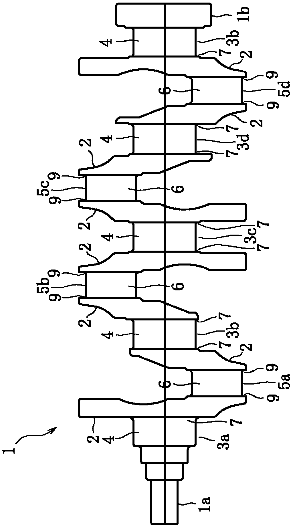
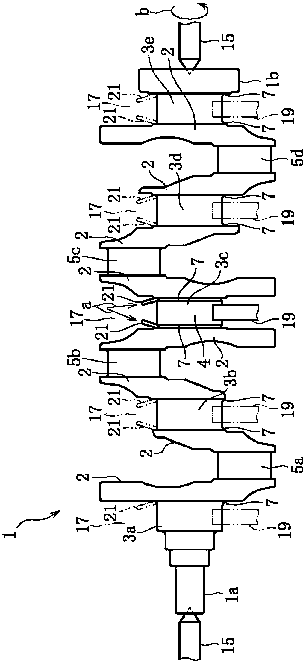
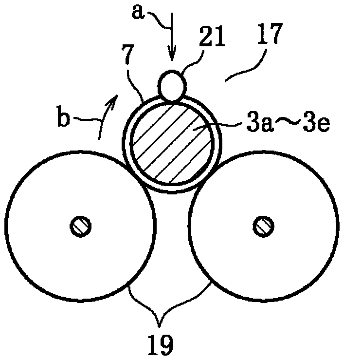
[0019] figure 1 Indicates the appearance of crankshaft 1. The crankshaft 1 is, for example, a crankshaft of a four-cylinder engine for a gasoline-powered vehicle. The crankshaft 1 includes, for example, from the left side, a No. 1 journal portion 3a (hereinafter referred to as journal portion 3a), a No. 1 pin portion 5a (hereinafter referred to as pin portion 5a), a No. 2 journal portion 3b (hereinafter referred to as journal portion 3b), and a No. 1 journal portion 3b (hereinafter referred to as journal portion 3b). ), No. 2 pin portion 5b (hereinafter referred to as pin portion 5b), No. 3 journal portion 3c (hereinafter referred to as journal portion 3c), No. 3 pin portion 5c (hereinafter referred to as pin portion 5c), No. 4 journal portion 3d ( Hereinafter, it is referred to as the journal portion 3d), the No. 4 pin portion 5d (hereinafter referred to as the pin por...


PUM


Abstract

A method of manufacturing a crankshaft according to the present invention is a method of manufacturing a crankshaft including a step of applying a predetermined roll to rounded corners (7, 9) of an axial end of a crank journal portion (3a to 3e) and an axial end of a crank pin portion (5a to 5d) (6) of the crank pin portions (5a to 5d), and a circle of the respective axial ends of the crankshaft journal portions (3a to 3e) after completion of the rolling process, And the corner portions (7, 9) are subjected to high-frequency quenching.

Description

technical field [0001] The invention relates to a method of manufacturing a crankshaft. Background technique [0002] In the crankshaft, due to the improvement of fatigue strength, wear resistance, etc., the sliding surface of the crankshaft journal and the sliding surface of the crankpin are generally subjected to induction hardening, and the axial direction of the crankshaft journal and the crankpin The rounded corners of the ends are each independently subjected to rolling (fillet rolling). [0003] Recently, in order to further improve the strength, wear resistance, etc. of the crankshaft, a method has been proposed (refer to Japanese Patent Application Laid-Open No. 2000-337345 ), and the crankshaft journal, the crankpin, and the crankshaft journal and The fillets at the axial ends of the crankpin are subjected to induction hardening to increase the surface hardness of each part, and then roll processing (fillet roll processing) is performed on each fillet. [0004] H...

Claims


Application Information

Patent Timeline
Patent Type & Authority Patents(China)
IPC IPC(8): B23P15/14
CPCB23P15/14B23P2700/07Y02P10/25
Inventor 谷口好正上野慎司小槻满男后藤一
Owner MITSUBISHI MOTORS CORP
Learn More