
high torque synchronizer

A synchronizer, high-torque technology, applied in clutches, mechanical drive clutches, mechanical equipment, etc., can solve problems such as short shift time and off-gear, and achieve the effect of improving reliability and stability

Active Publication Date: 2018-01-12
SHIYAN TONGCHUANG DRIVE TECH CO LTD
View PDF9 Cites 0 Cited by
  • Summary
  • Abstract
  • Description
  • Claims
  • Application Information

AI Technical Summary

Problems solved by technology

The synchronizer has good shifting performance and short shifting time, but since the top surfaces of the bosses are all sloped, the elastic pressure ring always has a pressing force on the synchronization ring, so when the vehicle is running bumpy, it is easy to lose gear.

Method used


Image

  • high torque synchronizer
  • high torque synchronizer
  • high torque synchronizer

Examples


Embodiment

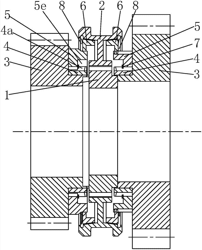
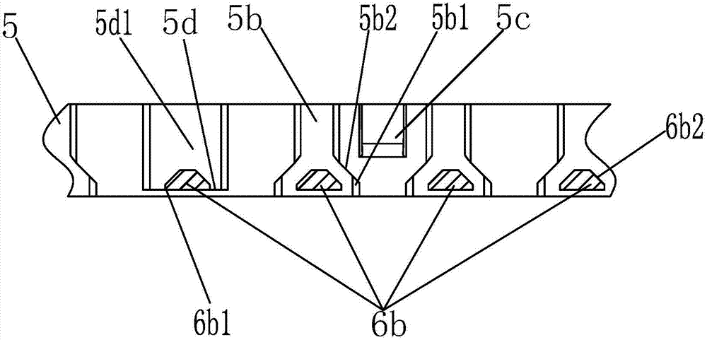
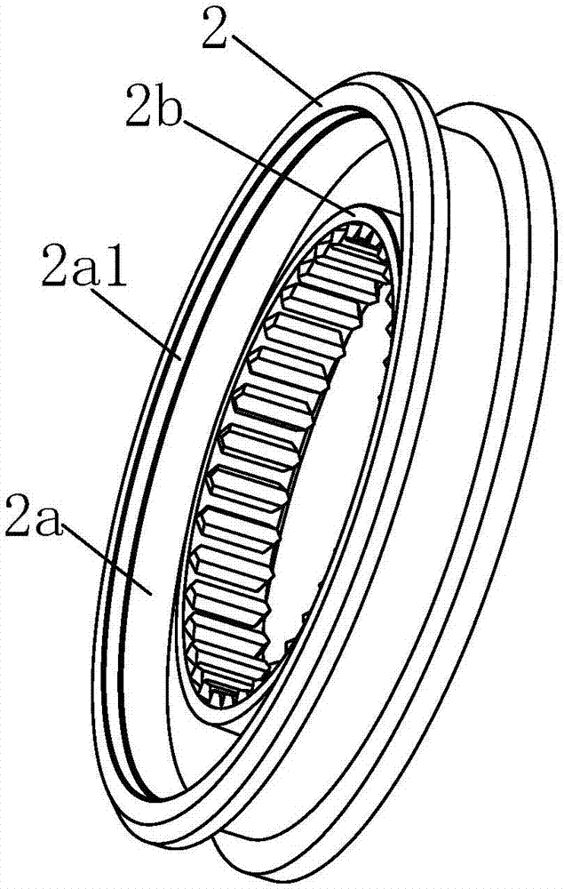
[0040] Embodiment: A high-torque synchronizer, including a gear hub 1, a gear sleeve 2 is slipped outside the gear hub 1, a gear gear 3 is arranged on both sides of the gear hub 1, two gears A combined ring gear 4 is fixed on the outer wall of the inner end of the bit gear 3, and a locking ring gear 5 is respectively set outside the two combined ring gears 4. The locking inner splines of the locking ring gear 5 5a is connected with the combined external spline groove 4a of the combined ring gear 4, and a synchronous ring 6 is respectively set outside the two locking ring gears 5, and the outer tapered surface 6a of the synchronous ring 6 is connected with the The inner tapered surface 2a cooperates, and the inner surface of the synchronous ring 6 is provided with spline teeth 6b along the circumferential direction, and the spline teeth 6b are respectively provided with tooth flanks 6b1 and locking surfaces 6b2, and the locking teeth The outer surface of the ring 5 is provided ...


PUM


Abstract

Provided is a large-torque synchronizer. The large-torque synchronizer comprises a gear hub which is sleeved with a gear sleeve. The two sides of the gear hub are each provided with a shifting gear. The outer wall of the inner end of each of the two shifting gears is provided with a combination gear ring. Each of the two combination gear rings is sleeved with a locking gear ring. Each of the two locking gear rings is sleeved with a synchronous ring. The outer conical face of each synchronous ring and the inner conical face of the corresponding gear sleeve are matched. Spline teeth are arranged on the inner surface of each synchronous ring in the peripheral direction. Each spline tooth is provided with a tooth side face and a locking face. The outer surface of each locking gear ring is provided with a spline tooth groove matched with the spline teeth of the corresponding synchronous ring. A spline tooth groove limiting face and a spline tooth groove locking face are sequentially arranged on the side face of the inner end of each spline tooth groove from inside to outside. A convex plate is arranged on the outer surface of each locking gear ring. The top face of each convex plate is provided with a convex plate arc face and a convex plate transitional slope. Each convex plate arc face and the outer surface of the corresponding locking gear ring are arranged coaxially. A reset groove is formed in the position, corresponding to an elastic pressing ring, of each inner conical face and can drive the elastic pressing ring to reset. The large-torque synchronizer is suitable for gearboxes.

Description

technical field [0001] The invention relates to the field of synchronizers, in particular to a high-torque synchronizer. Background technique [0002] When the gearbox is shifting gears, the speeds of the teeth of the two gears are often out of sync. If they are forced to mesh, it will cause strong impact and harsh noise between the teeth, which will not only hinder the shifting of gears, but also aggravate the wear of the ends of the teeth. . Therefore, the problem to be solved urgently when shifting gears is to ensure that the rotation speed of a pair of gear teeth to be meshed is synchronized in the selected gear position, so a synchronizer is produced. [0003] The synchronizer is an important part of the automobile transmission. It makes the input and output parts of the synchronizer synchronized and then combined, thereby reducing the impact and noise when shifting gears, reducing the shifting force, making the shifting smooth and light, and reducing the driver's fati...

Claims


Application Information

Patent Timeline
Patent Type & Authority Patents(China)
IPC IPC(8): F16D23/06
CPCF16D23/025F16D23/06F16D2023/0625F16D2023/0656
Inventor 杨宏伟吴峰
Owner SHIYAN TONGCHUANG DRIVE TECH CO LTD
Learn More