a clip light

A clip lamp and lamp body technology, which is applied to lighting devices, electric light sources, lighting device components, etc., can solve the problems of limited installation methods, single fixed form, and large volume, and achieve light weight, various fixed forms, and easy to use convenient effect

Inactive Publication Date: 2018-05-29
杭州泰舸奥途实业有限公司
View PDF7 Cites 0 Cited by
  • Summary
  • Abstract
  • Description
  • Claims
  • Application Information

AI Technical Summary

Problems solved by technology

[0002] The lamp is usually connected with a heavy base, and the base is placed on the ground or on the table. The lamp is generally large in size and needs to be placed on a flat ground or table. The installation method is limited, the fixed form is relatively single, and the use is not flexible enough.

Method used


Image

  • a clip light
  • a clip light
  • a clip light

Examples


Embodiment Construction

[0028] In order to further explain the technical solution of the present invention, the present invention will be described in detail below through specific examples.

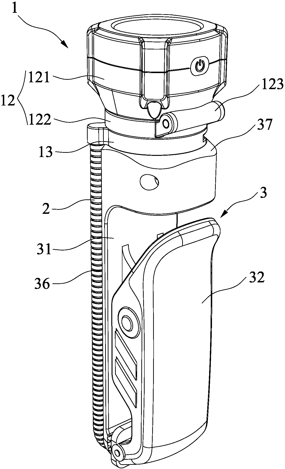
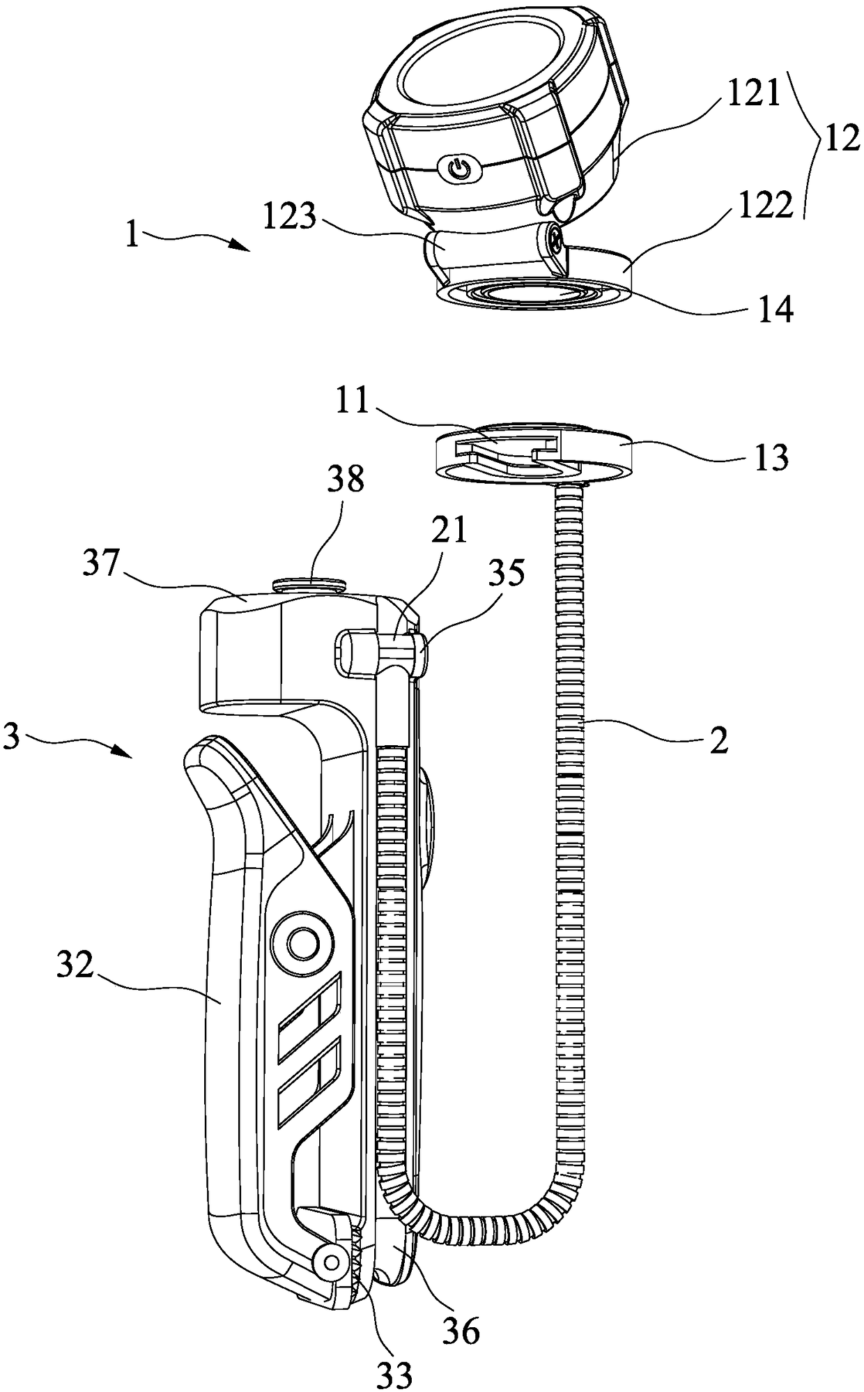
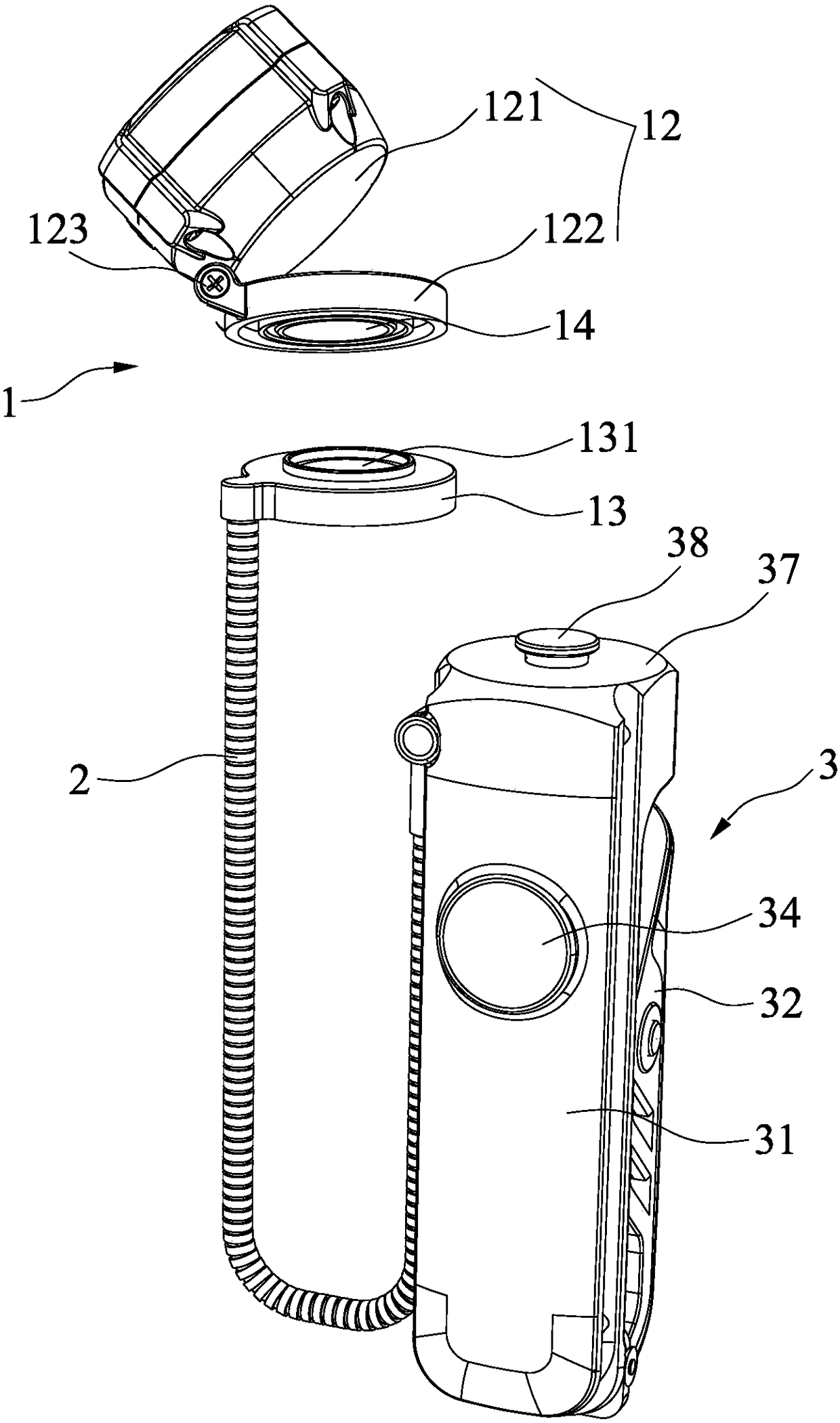
[0029] Such as Figure 1-4 Shown is a clip lamp disclosed by the present invention, including a lamp body 1, a hose 2 and a fixing clip 3.

[0030] The lamp body 1 is connected by a hose 2 and a fixing clip 3. The hose 2 in this embodiment is preferably a common serpentine hose, and the serpentine hose has the characteristic that it can be fixed at any position. Meanwhile, the lamp body 1 is detachably installed on the fixing clip 3 .

[0031] The fixing clip 3 has a clip seat 31 and a clamping plate 32, and there are many fixing clips 3 with this structure, and will not be described one by one here. The preferred structure of the fixing clamp 3 in this embodiment is that one end of the clamping plate 32 is mounted on the clamping seat 31 through a rotating shaft and a torsion spring. In order to increase th...


PUM


Abstract

The invention discloses a clamp lamp. The clamp lamp comprises a lamp body, a hose and a fixing clamp. The lamp body is detachably installed on the fixing clamp with a clamp base and a clamp plate. Meanwhile, the lamp body is connected with the fixing clamp through the hose. The clamp lamp is small in weight and has various fixing forms, using is very convenient and flexible, and the lamp can be rotated in any direction.

Description

technical field [0001] The invention relates to the technical field of lamps, in particular to a clip lamp. Background technique [0002] The lamp is generally connected with a heavy base, and the base is placed on the ground or a table. The lamp is generally large in size and needs to be placed on a flat ground or table. The installation method is limited, the fixed form is relatively single, and the use is not flexible enough. [0003] In view of this, the inventor has developed a clip lamp for this purpose, which effectively solves the above-mentioned problems, and this case arises from it. Contents of the invention [0004] The clip lamp provided by the present invention is light in weight, has multiple fixing forms, is very convenient and flexible to use, and the lamp can be rotated in any direction. [0005] In order to achieve the above object, the technical scheme of the present invention is as follows: [0006] A clip lamp includes a lamp body, a hose and a fixi...

Claims


Application Information

Patent Timeline
Patent Type & Authority Patents(China)
IPC IPC(8): F21S2/00F21V21/088F21V21/096F21V21/14F21V21/32
CPCF21S2/00F21V21/088F21V21/096F21V21/14F21V21/32
Inventor 郑沈洁
Owner 杭州泰舸奥途实业有限公司
Why Eureka
Try Eureka