Concentric dual clutch device

A dual-clutch, clutch technology, applied in clutches, fluid-driven clutches, mechanical-driven clutches, etc., can solve the problems of small axial total length, large axial total length, etc.

Active Publication Date: 2018-01-26
BORGWARNER INC
View PDF8 Cites 0 Cited by
  • Summary
  • Abstract
  • Description
  • Claims
  • Application Information

AI Technical Summary

Problems solved by technology

The known concentric double clutch arrangement has proven its worth, but has the disadvantage that it has a relatively large overall axial length
The known concentric double clutch arrangement has already proven its worth, since it can achieve a particularly small axial overall length, but again a relatively large force transmission path through the force transmission element has to be accepted, in addition, more precisely Point force transmission to the outer multi-plate clutch and its plate pack is possible via the actuation of the force transmission element

Method used


Image

  • Concentric dual clutch device
  • Concentric dual clutch device
  • Concentric dual clutch device

Examples


Embodiment Construction

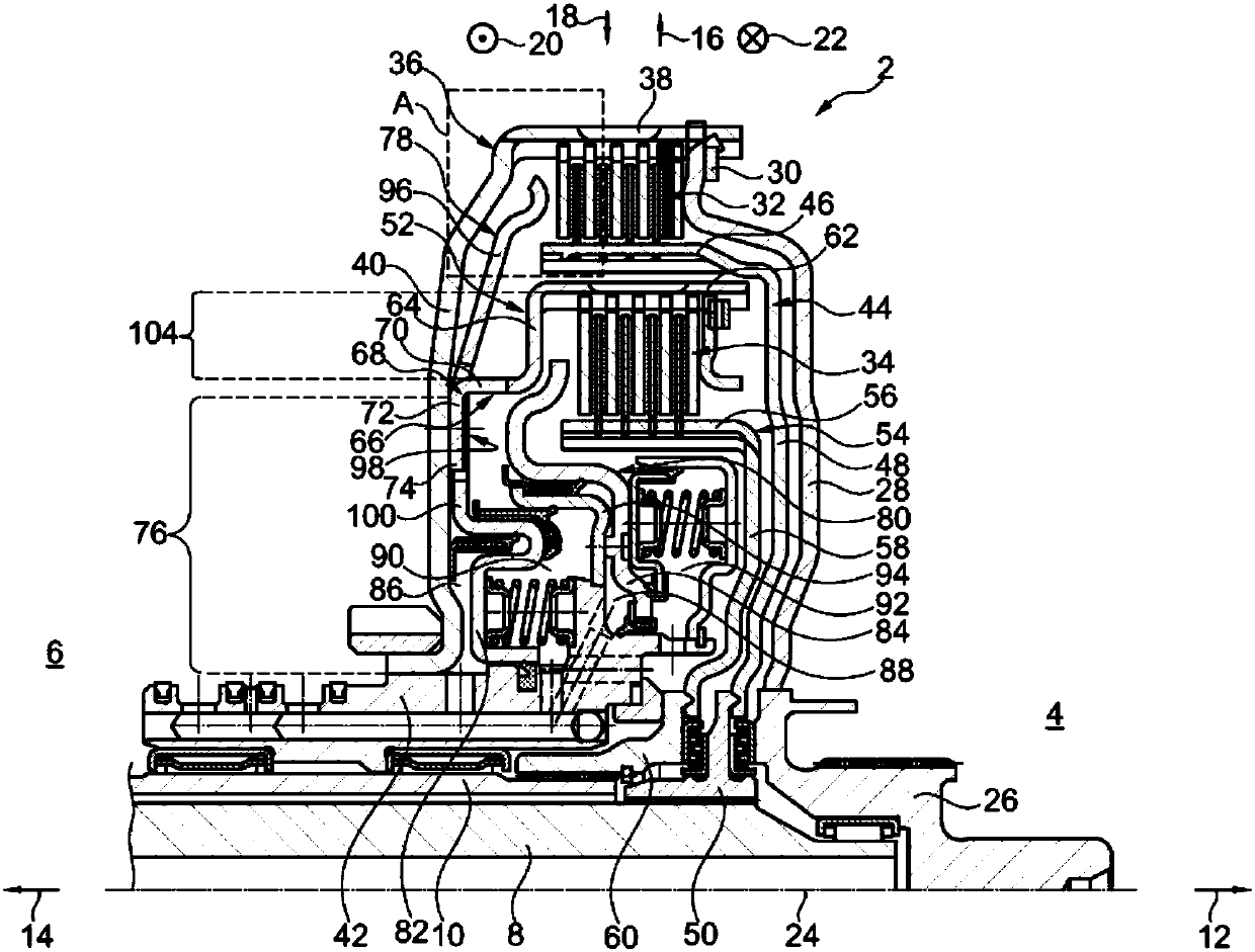
[0032] figure 1 A concentric dual clutch arrangement 2 is shown for arrangement in the drive train of a motor vehicle between a drive unit 4 , preferably an internal combustion engine, and a transmission 6 , wherein the drive unit 4 and the transmission 6 are only indicated schematically. The other parts of the transmission 6 shown are a first transmission input shaft 8 and a second transmission input shaft 10, wherein the second transmission input shaft 10 is designed as a hollow shaft through which the first transmission input shaft 8 extends, and They can therefore also be referred to as concentrically arranged transmission input shafts 8 , 10 . In the figures, mutually opposite axial directions 12, 14, mutually opposite radial directions 16, 18 and mutually opposite circumferential directions 20, 22 of the dual clutch device 2 are indicated by means of corresponding arrows, wherein the circumferential directions 20, 22 are also This can be referred to as a rotational dire...


PUM


Abstract

The invention relates to a concentric double clutch arrangement (2) arranged between a drive unit (4) and a transmission (6) in a drive train of a motor vehicle, the clutch arrangement having an outer multi-plate clutch (32) and an inner A multi-plate clutch (34), an outer multi-plate clutch (32) is distributed to the first transmission input shaft (8) for selectivity between the drive unit (4) and the first transmission input shaft (8) Torque transfer, the inner multi-plate clutch (34) is distributed to the second transmission input shaft (10) for selective torque transfer between the drive unit (4) and the second transmission input shaft (10), wherein the inner The multi-plate clutch (34) distributes the inner outer plate carrier (52) and the outer multi-plate clutch (32) distributes the force transmission element (78) for transmitting the actuating force to said outer multi-plate clutch (32) , and the inner outer plate support (52) extends through a hole or window (102) in the force transmission element (78).

Description

technical field [0001] The invention relates to a concentric dual clutch arrangement which is arranged in the drive train of a motor vehicle between a drive unit and a transmission. The clutch arrangement has an outer multi-plate clutch distributed to the first transmission input shaft for selective torque transmission between the drive unit and the first transmission input shaft and an inner multi-plate clutch The inner multi-plate clutch is assigned to the second transmission input shaft for selective torque transfer between the drive unit and the second transmission input shaft, wherein the inner multi-plate clutch is assigned to the inner outer plate carrier and the outer multi-plate clutch is assigned to the The force transmission element that transmits the actuation force to the outer multi-plate clutch. Background technique [0002] EP 2 158 413 B1 discloses a concentric double clutch arrangement arranged in the drive train of a motor vehicle between a drive unit and...

Claims


Application Information

Patent Timeline
Patent Type & Authority Patents(China)
IPC IPC(8): F16D25/10F16D25/0638
CPCF16D2021/0661F16D2300/26F16D25/0638F16D25/10
Inventor H·J·豪克
Owner BORGWARNER INC
Why Eureka
Try Eureka