
Hydrostatic drive system with pump-sided division of the amount of hydraulic fluid for two hydraulic circuits

A technology of hydraulic fluid and transmission system, applied in the direction of fluid transmission, transmission, transmission control, etc., can solve the problems of long axial total length and so on

Inactive Publication Date: 2008-07-30
HYDROMATIK GMBH
View PDF6 Cites 0 Cited by
  • Summary
  • Abstract
  • Description
  • Claims
  • Application Information

AI Technical Summary

Problems solved by technology

[0004] Moreover, the disadvantage of the hydrostatic stroke transmission in EP 0 378 742 A2 is the use of two separate hydraulic pumps for the two hydraulic circuits, and the resulting long overall axial length

Method used


Image

  • Hydrostatic drive system with pump-sided division of the amount of hydraulic fluid for two hydraulic circuits
  • Hydrostatic drive system with pump-sided division of the amount of hydraulic fluid for two hydraulic circuits
  • Hydrostatic drive system with pump-sided division of the amount of hydraulic fluid for two hydraulic circuits

Examples


Embodiment Construction

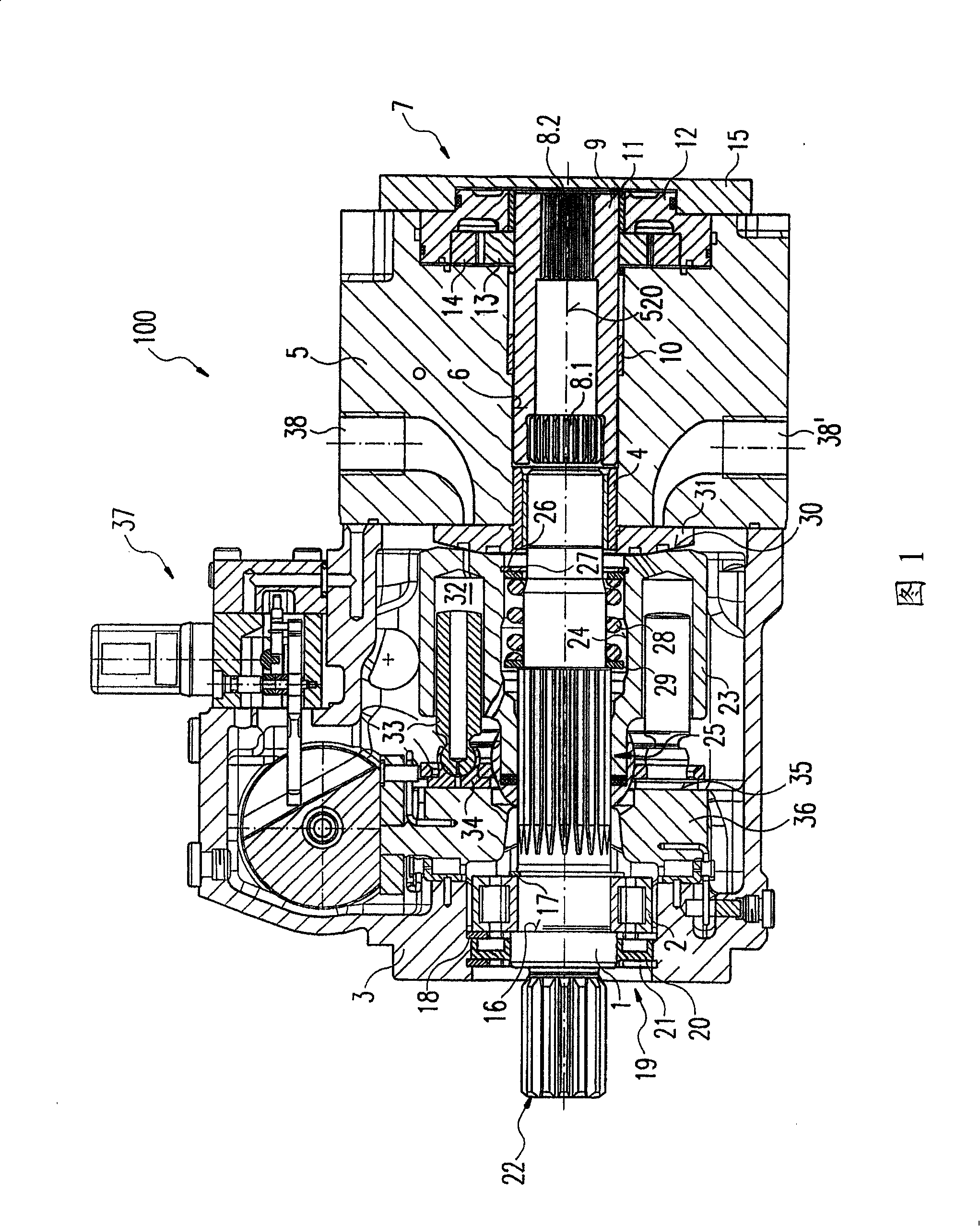
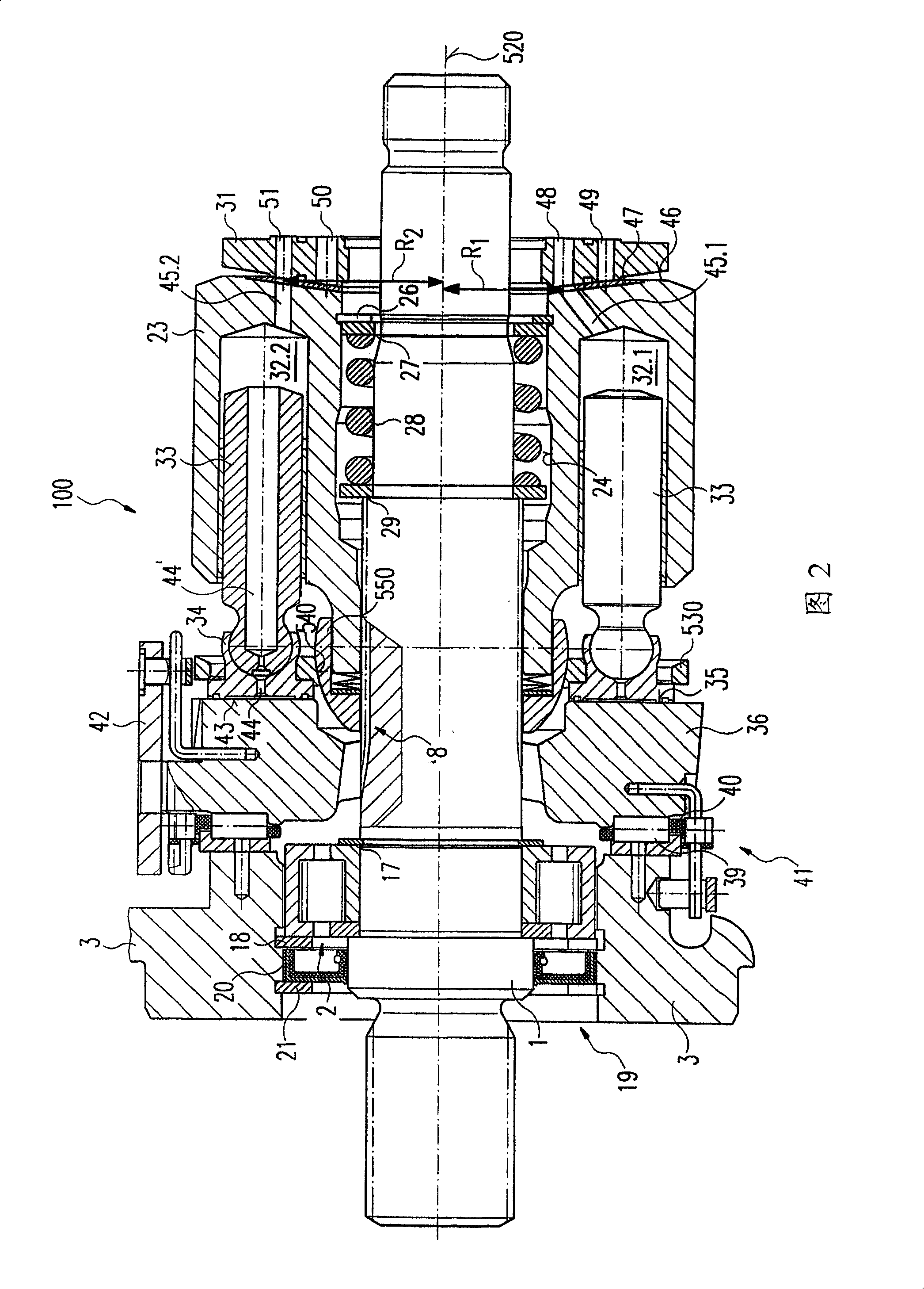
[0015] Referring now to FIGS. 1 and 2 , an exemplary embodiment of a hydraulic pump 100 according to the present invention with a hydraulic transmission system that distributes the amount of hydraulic fluid in the pump is illustrated.

[0016] The longitudinal section of the hydraulic pump 100 shown in FIG. 1 shows how the common transmission shaft 1 is mounted through a roller bearing 2 at one end of the pump housing 3 . The common transmission shaft 1 is additionally mounted in a slide bearing 4 arranged in a web 5 , which closes the opposite end of the pump housing 3 .

[0017] Formed in the connecting plate 5 is a hole 6 extending axially from the right through the connecting plate, in which on the one hand the plain bearing 4 is accommodated and on the other hand the common transmission shaft 1 passes through the hole 6 . On the side of the connecting plate 5 facing away from the pump housing 3 , the auxiliary pump 7 is inserted in a radial widening in the bore 6 . To dr...


PUM


Abstract

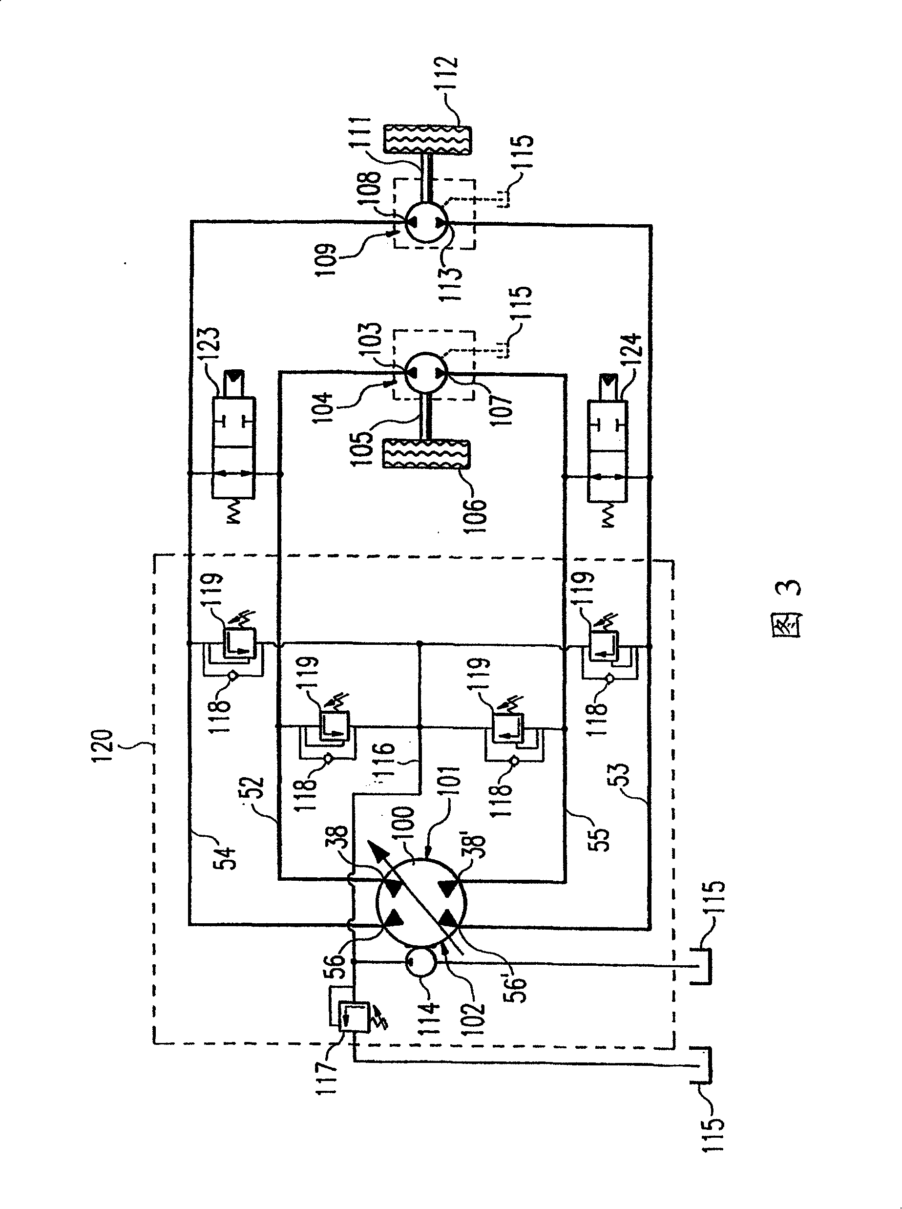
A hydrostatic drive system comprising at least one hydropump (100) and at least two hydromotors (104,109). The hydropump (100) divides its total hydraulic fluid flow into at least two partial hydraulic fluid flows which are respectively pumped in the form of a partial pump train (101,102) in a common cylinder drum (23) of the hydropump (100). The first connection (103) of a first hydromotor (104), which drives a first drive train (105), is connected to the first connection (38) of the first partial pump train (101) of the hydropump (100) and the second connection (107) thereof is connected to the second connection (38'') of the first pump train (101) of the hydropump (100). The first connection (108) of a second hydromotor (109) which drives a second drive train (111) is connected to the first connection (56) of the second partial pump train (102) of the hydropump (100) and the second connection (113) thereof is connected to the second connection (56') of the second partial pump strain (102) of the hydropump (100).

Description

technical field [0001] The invention relates to a hydrostatic drive system for two hydraulic circuits with a pump-side hydraulic fluid quantity distribution. Background technique [0002] As described in EP 0 378 742 A2, a hydraulic stroke transmission designed for cornering maneuvers has two mutually separated hydraulic circuits, each consisting of a hydraulic pump and a hydraulic motor. In this way, different amounts of hydraulic fluid can be separately delivered to the two hydraulic motors by the two hydraulic pumps in the case of a turning operation performed by the hydraulic stroke transmission. [0003] The hydraulic stroke transmission according to EP 0 378 742 A2 is characterized in that it is difficult to deliver the same amount of hydraulic fluid required for straight-ahead travel to the two hydraulic motors by means of two hydraulic pumps. This difficulty is compounded by the fact that, in the case of straight travel through a hydraulic stroke transmission, if on...

Claims


Application Information

Patent Timeline
Patent Type & Authority Patents(China)
IPC IPC(8): B60K17/10F04B1/22F04B23/06F16H61/44F16H39/02B60K7/00F04B1/20F16H61/4078F16H61/456
CPCF04B1/22F16H61/456B60K7/0015B60K17/10F16H61/44F04B23/06F04B1/20
Inventor 诺伯特·鲁克高尔海因茨-格哈德·艾西格
Owner HYDROMATIK GMBH
Learn More