Electric connector

A technology of electrical connectors and electrical connections, which is applied in the direction of connections, circuits, parts of connection devices, etc., which can solve the problems of complicated operation, inconvenient replacement or maintenance of electronic components, and achieve the effect of convenient replacement or maintenance

Inactive Publication Date: 2016-10-19
TYCO ELECTRONICS (SHANGHAI) CO LTD
View PDF7 Cites 2 Cited by
  • Summary
  • Abstract
  • Description
  • Claims
  • Application Information

AI Technical Summary

Problems solved by technology

However, the disadvantage of this solution is that the operation is complicated

Method used


Image

  • Electric connector
  • Electric connector
  • Electric connector

Examples


Example Embodiment

[0028] In the following, the technical solutions of the present invention will be further described in detail through embodiments and in conjunction with the drawings. In the specification, the same or similar reference numerals indicate the same or similar components. The following description of the embodiments of the present invention with reference to the accompanying drawings is intended to explain the general inventive concept of the present invention, and should not be understood as a limitation to the present invention.

[0029] In addition, in the following detailed description, for the convenience of explanation, many specific details are set forth to provide a comprehensive understanding of the embodiments of the present disclosure. Obviously, however, one or more embodiments can also be implemented without these specific details. In other cases, well-known structures and devices are shown in the form of illustrations to simplify the drawings.

[0030] According to a g...


PUM


Abstract

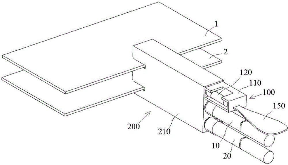
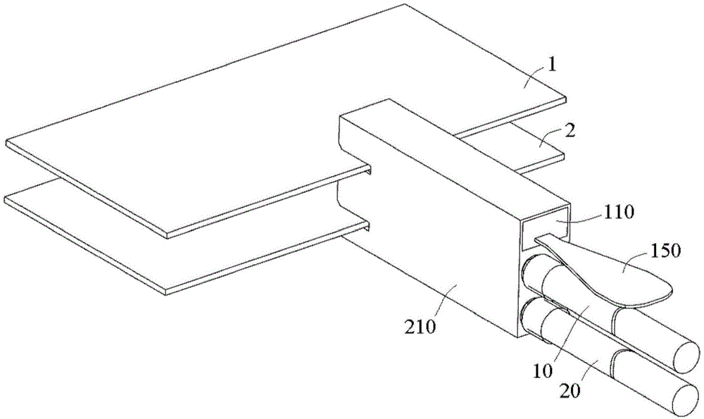
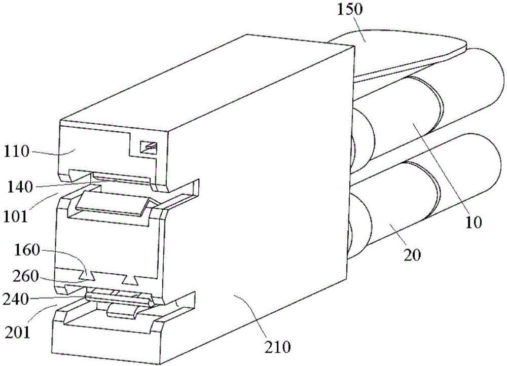
The invention discloses an electric connector, comprising a first module and a second module; the first module comprises a first insulation body and an electronic member contained in the first insulation body; the second module comprises a second insulation body; the first module is assembled in the second module in a manner of moving relatively to the second module; and the electronic member contained in the first insulation body can be moved to the outside of the second insulation body. When replacement or maintenance of the electronic member is needed, at least part of the first insulation body of the first module can be moved to the outside of the second insulation body of the second module and the electronic member contained in the first insulation body can be moved to the outside of the second insulation body, so that the replacement and maintenance for the electronic member can be performed.

Description

technical field [0001] The invention relates to an electrical connector. Background technique [0002] An electrical connector generally includes an insulating body and conductive terminals and electronic components accommodated in the insulating body. [0003] In some technical solutions of the prior art, the insulating body is usually a molded integral piece, and the electronic components are molded inside the insulating body. If the electronic components fail, the electronic components cannot be replaced or maintained, resulting in the entire electrical connector If it is scrapped, it needs to be replaced with a new electrical connector, which will lead to a waste of resources and an increase in cost. [0004] In order to solve the aforementioned problems, in other technical solutions of the prior art, the insulating body is divided into an insulating base and an insulating upper cover. The insulating upper cover is fixedly mounted to the frame base, for example, by mea...

Claims


Application Information

Patent Timeline
IPC IPC(8): H01R13/688H01R13/629H01R13/514
Inventor 李华
Owner TYCO ELECTRONICS (SHANGHAI) CO LTD
Why Eureka
Try Eureka