Novel super-large transverse displacement modular multi-directional displacement expansion joint

A technology of lateral displacement and multi-directional displacement, applied in the directions of bridge parts, bridges, buildings, etc., can solve the problems of small displacement change, reduce the service life of bridge expansion joints, affect the normal operation of bridge expansion joints, etc., and achieve increased stability. performance, guaranteeing the effect of scalability

Pending Publication Date: 2019-05-21
天津桥通科技发展有限公司
View PDF5 Cites 2 Cited by
  • Summary
  • Abstract
  • Description
  • Claims
  • Application Information

AI Technical Summary

Problems solved by technology

[0003] At present, the same kind of bridge expansion joints only use the tooth spacing between the comb teeth to realize the change of lateral displacement. However, the range of displacement change is small. For some extreme natural phenomena, such as earthquakes, the existing bridge expansion joints cannot meet the requirements. The requirement of super large lateral displacement change, the displacement beyond the rated displacement range of the expansion joint will affect the normal operation of the bridge expansion joint and reduce the service life of the bridge expansion joint

Method used


Image

  • Novel super-large transverse displacement modular multi-directional displacement expansion joint
  • Novel super-large transverse displacement modular multi-directional displacement expansion joint
  • Novel super-large transverse displacement modular multi-directional displacement expansion joint

Examples


Embodiment Construction

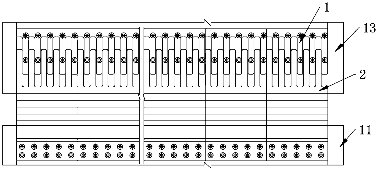
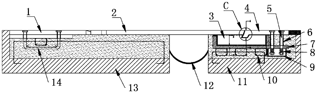
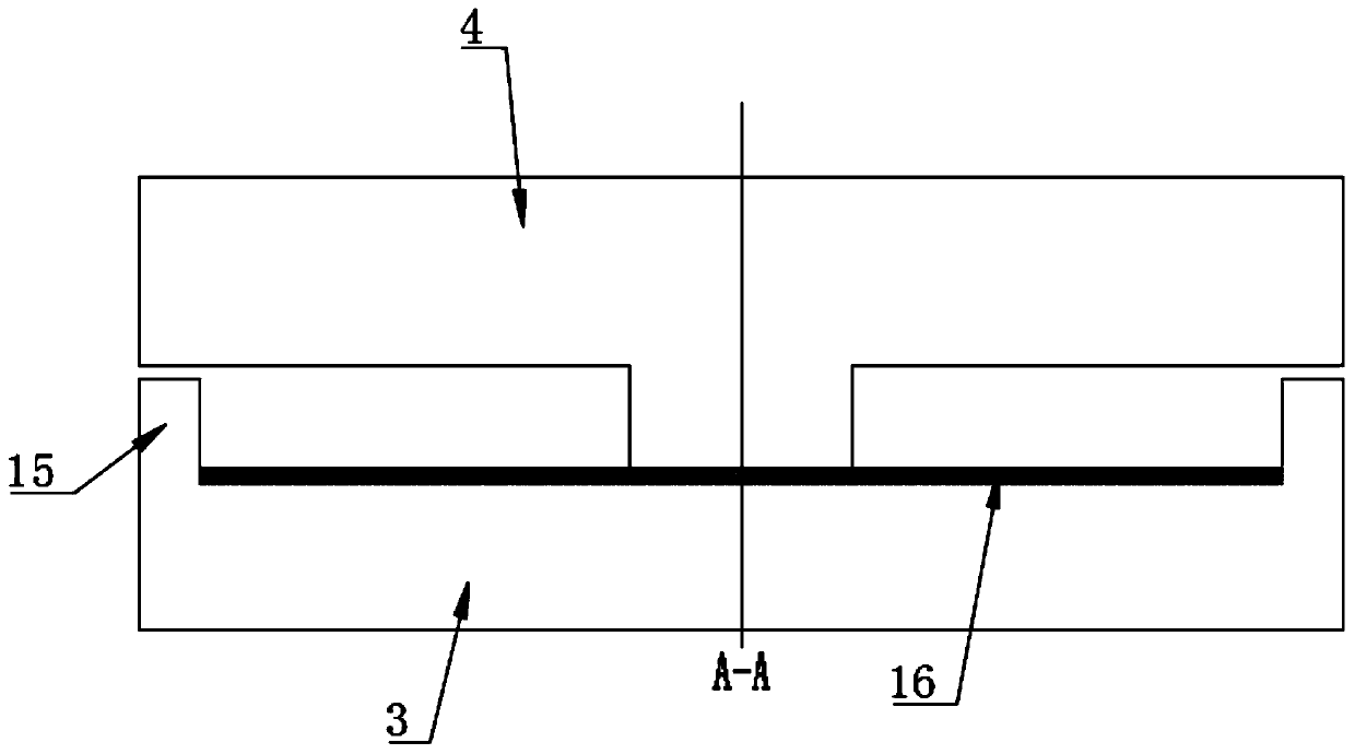
[0030] Such as Figure 1 to Figure 6 As shown, a novel super large lateral displacement modular multi-directional displacement expansion joint of the present invention includes a main tooth plate 2 and an auxiliary tooth plate 1. The comb teeth of the main tooth plate 2 and the auxiliary tooth plate 1 cross each other and have gaps. One end of the tooth plate 2 is erected on the first bridge beam body 11, and the other end spans the gap between the first bridge beam body 11 and the second bridge beam body 13 and is installed on the second bridge beam body 13. The auxiliary tooth plate 1 is installed on the second bridge girder body 13, and the bottom surface of the main tooth plate 2 erected on the first bridge girder body 11 is fixedly connected with one part of the top surface of the lateral displacement plate 3, and the other part of the top surface of the lateral displacement plate 3 , the main teeth are connected with one end of the displacement plate cover plate 4 respec...


PUM


Abstract

The invention relates to a novel super-large transverse displacement modular multi-directional displacement expansion joint, which comprises a main toothed plate, an auxiliary toothed plate, a first bridge beam body and a second bridge beam body, wherein the bottom surface of the main toothed plate which is arranged on the first bridge beam body is fixedly connected with one part of the top surface of a transverse displacement plate; the other part of the top surface of the transverse displacement plate and the main teeth are respectively connected with one end of a displacement plate cover plate in a matching way; the other end of the displacement plate cover plate is fixedly connected with the first bridge beam body; a chute is formed in another portion of the top surface of the transverse displacement plate; the side of the main toothed plate that cooperates with the displacement plate cover is a first oblique side; the two sides of the chute that cooperate with the displacement plate cover are second oblique sides; the angle between the first oblique side and the vertical plane is smaller than the angle between each second oblique side and the vertical plane; the outer periphery of the transverse displacement plate is provided with a fixed base that is coupled to and fixed to the first bridge beam body. The novel super-large transverse displacement modular multi-directionaldisplacement expansion joint can achieve that the transverse displacement variation is at least+/-500mm under the extreme condition.

Description

technical field [0001] The invention relates to the technical field of bridge construction, in particular to a novel ultra-large transverse displacement modular multi-directional displacement expansion joint. Background technique [0002] In order to meet the needs of bridge girder deformation, bridge expansion joints are generally installed between the two girder ends of the bridge, between the girder end and the abutment, or at the hinge position of the bridge. With the development of road transportation, road traffic volume and The load of automobiles is getting bigger and bigger, and the performance requirements for the expansion and contraction of highway bridges are constantly improving. [0003] At present, the same kind of bridge expansion joints only use the tooth spacing between the comb teeth to realize the change of lateral displacement. However, the range of displacement change is small. For some extreme natural phenomena, such as earthquakes, the existing bridg...

Claims


Application Information

Patent Timeline
Patent Type & Authority Applications(China)
IPC IPC(8): E01D19/06
Inventor 田欣
Owner 天津桥通科技发展有限公司
Why Eureka
Try Eureka