Rebar cutting device with automatic measuring and marking functions

A cutting device, automatic measurement technology, applied in metal processing, metal processing equipment, manufacturing tools and other directions, can solve the problems of troublesome operation, low degree of automation, trouble, etc., to achieve convenient identification and detection, improve work efficiency, high efficiency Effect

Inactive Publication Date: 2016-10-26
陈泳东
View PDF7 Cites 1 Cited by
  • Summary
  • Abstract
  • Description
  • Claims
  • Application Information

AI Technical Summary

Problems solved by technology

[0002] With the rise of modern buildings, concrete structures mixed with steel bars and cement have become the main structure of modern buildings, so the use of steel bars is also increasing year by year, especially in recent years, the use of steel bars in buildings is increasing , but when the steel bar is used, the steel bar is not directly put into the formwork. It needs to be precisely cut and welded to form a complete skeleton structure before it can be placed in the formwork. Therefore, on the modern construction site, the cutting of the steel bar is a Very important and troublesome, time-consuming and labor-intensive
[0003] Existing cutting equipment relies on manual operation to a large extent, and the degree of automation is low. Workers are required to measure and feed materials before each cutting, which is troublesome to operate. When it is used to cut a large number of straight steel bars, workers Labor intensity is high, and the efficiency of shearing is low

Method used


Image

  • Rebar cutting device with automatic measuring and marking functions
  • Rebar cutting device with automatic measuring and marking functions

Examples


Embodiment

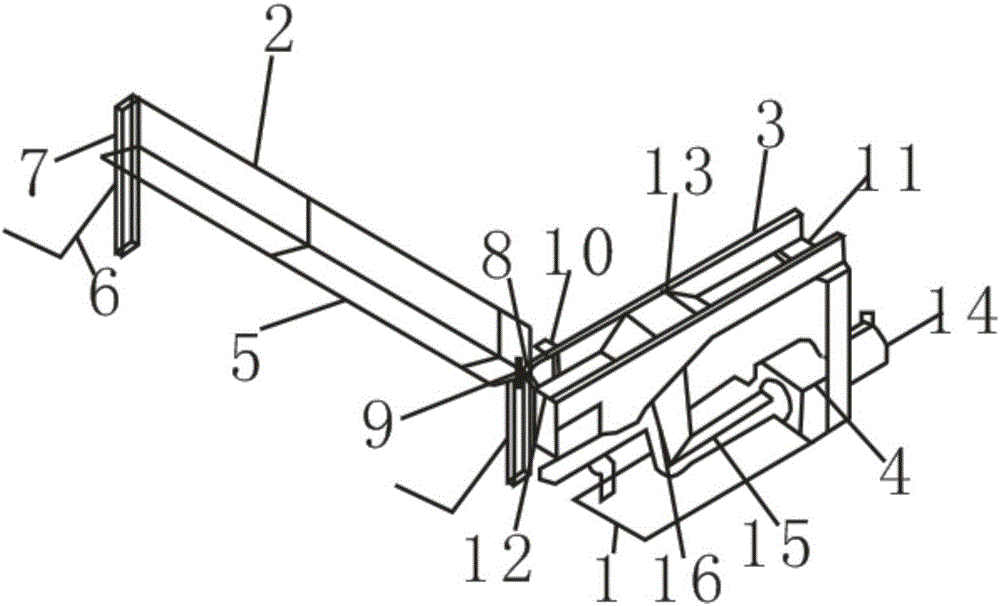
[0015] see figure 1 and figure 2 The present invention provides a technical solution: a steel bar cutting device for automatically measuring marks, including a cutting base 1, a feeding device 2, a cutting device 3 and a driving device 4, and the cutting device 3 and the driving device 4 are fixed on the cutting base 1 The upper surface of the upper surface can be more stable during cutting and driving, reducing vibration and improving stability, and the cutting device 3 is arranged above the driving device 4, which is convenient for the driving device 4 to provide power, and makes full use of the occupied space, reduces the volume of the device, and further The feeding device 2 includes a feed hopper 5 and a support column 7, the feed hopper 5 is made into a "V" shape, the feed hopper 5 is fixedly installed on the support column 7, and a steel bar hook 6 is installed on the feed hopper 7, Through the making effect of the support column 7, the feed hopper 5 and the steel bar...


PUM


Abstract

The invention discloses a rebar cutting device with automatic measuring and marking functions. The rebar cutting device comprises a cutting base, a feeding device, a cutting device and a driving device. The cutting device and the driving device are both fixed to the upper surface of the cutting base, the feeding device comprises a feeding hopper and a supporting column, a positioning retaining plate is fixedly mounted at the top of the feeding hopper and connected with an automatic cut-to-length measurer, and a marker is mounted on the lateral side of the automatic cut-to-length measurer. The cutting device consists of a cutter and a power shaft, the cutter comprises a cutting opening and a cutting knife in the cutting opening, and the cutter knife is driven by the power shaft. The driving device comprises a driving motor and a transmission shaft. Automatic feeding can be realized, the rebar cutting device has a measurement function intrinsically, measurement precision is high due to an alignment function, cutting is directly performed after measurement, and simplicity and convenience are achieved; length marks are left after rebar measurement to make it convenient for recognition and detection of cutting errors, and operation efficiency is improved.

Description

technical field [0001] The invention relates to the technical field of construction equipment, in particular to a steel bar cutting device for automatically measuring marks. Background technique [0002] With the rise of modern buildings, concrete structures mixed with steel bars and cement have become the main structure of modern buildings, so the use of steel bars is also increasing year by year, especially in recent years, the use of steel bars in buildings is increasing , but when the steel bar is used, the steel bar is not directly put into the formwork. It needs to be precisely cut and welded to form a complete skeleton structure before it can be put into the formwork. Therefore, on the modern construction site, the cutting of the steel bar is a It is very important and troublesome, time-consuming and labor-intensive. [0003] Existing cutting equipment relies on manual operation to a large extent, and the degree of automation is low. Workers are required to measure a...

Claims


Application Information

Patent Timeline
Patent Type & Authority Applications(China)
IPC IPC(8): B21F11/00B21F23/00B21C51/00
CPCB21F11/00B21C51/00B21F23/007
Inventor 陈泳东
Owner 陈泳东
Why Eureka
Try Eureka