Apparatus and method for measuring dynamic target modulation transfer function

A technology of modulation transfer function and measurement method, which is applied in the direction of testing optical performance, etc., and can solve problems such as inability to separate out and error in measurement results

Inactive Publication Date: 2010-09-29
江苏亚星波纹管有限公司
View PDF0 Cites 0 Cited by
  • Summary
  • Abstract
  • Description
  • Claims
  • Application Information

AI Technical Summary

Problems solved by technology

Its shortcoming is that these two articles only conduct mathematical derivation and simulation on the dynamic target modulation transfer function, and do not actually measure it
And its shortcoming is that this experimental device can only complete the measurement of the modulation transfer function of the dynamic target of low-frequency simple harmonic motion and cannot take into account the measurement of the dynamic target modulation transfer function of other forms of motion; moreover, the final measurement result of this experimental device is The modulation transfer function of simple harmonic motion and the entire imaging system, and the influence of the imaging system itself on the reduction of the transfer function curve cannot be separated from the measurement results; the most important thing is that this experimental device uses a uniform linear motion dynamic target If the modulation transfer function measurement results are used to replace the modulation transfer function of the low-frequency simple harmonic motion dynamic target, the measurement results will have a large error

Method used


Image

  • Apparatus and method for measuring dynamic target modulation transfer function
  • Apparatus and method for measuring dynamic target modulation transfer function
  • Apparatus and method for measuring dynamic target modulation transfer function

Examples


Embodiment Construction

[0038] The specific embodiments of the present invention will be further described in detail below in conjunction with the accompanying drawings.

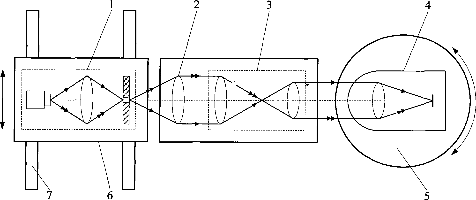
[0039] In this example, the light source 1 and the image sensor in the photoelectric imaging system 4 are respectively a combination of a point light source and an area array image sensor to complete the measurement of the modulation transfer function of a dynamic target moving in a straight line with a uniform velocity at a field of view of 0 degrees. figure 1 For the dynamic target modulation transfer function measurement device described in the present invention, a light source 1, a collimating objective lens 2, a pupil coupling system 3, and a photoelectric imaging system 4 are placed in sequence along the light propagation direction. The light source 1 is placed on the slider 6 that can move along the direction of the guide rail 7, and the photoelectric imaging system 4 is placed on the precision turntable 5, wherein the light...


PUM


Abstract

The invention relates to a dynamic object modulation transfer function measuring method and a device thereof, pertaining to the optical property measurement field. The invention aims at providing a dynamic object modulation transfer function measuring method and a device thereof which can carry out the dynamic object modulation transfer function measurement under different fields of view, namely,uniform linear motion, uniformly-accelerated rectilinear motion, simple harmonic motion, but also can measure static target modulation transfer function and separate the static target modulation transfer function from whole machine modulation transfer function. The device consists of a light source, a collimating lens, a pupil coupling system and an electro-optical imaging system which are arranged along the ray propagation direction in sequence; the electro-optical imaging system carries out imaging towards the light source moving along the guide rail direction and line spread function is obtained from the image and carried out one-dimensional Fourier transformation so as to obtain the dynamic object modulation transfer function. The method and the device of the invention are not only suitable for static image evaluation field but also for the image evaluation field of dynamic object imaging by a time-delay electro-optical imaging system.

Description

technical field [0001] The invention relates to a method and a device for measuring an optical transfer function in the field of optical property testing, in particular to a method and a device for measuring a dynamic target modulation transfer function. Background technique [0002] Modulation transfer function is an important means to evaluate the system information transfer capability. In the field of optics, the modulation transfer function is used to describe the ability of an optical system to transmit image information. The modulation transfer function measurement technology began in 1955, and its test method is characterized by using still images as the information source to evaluate the transfer ability of the optical mirror group. However, with the development and application of photoelectric tracking systems, time-lapse imaging devices represented by CCDs have been widely used, such as aerial photography technology and optical imaging guidance technology. In the...

Claims


Application Information

Patent Timeline
Patent Type & Authority Patents(China)
IPC IPC(8): G01M11/02
Inventor 刘俭谭久彬赵烟桥胡斌张大庆
Owner 江苏亚星波纹管有限公司
Why Eureka
Try Eureka